
Reconfigurable multi-cell power converter

Active Publication Date: 2010-12-16
RAYTHEON CO
View PDF12 Cites 52 Cited by
  • Summary
  • Abstract
  • Description
  • Claims
  • Application Information

AI Technical Summary

Benefits of technology

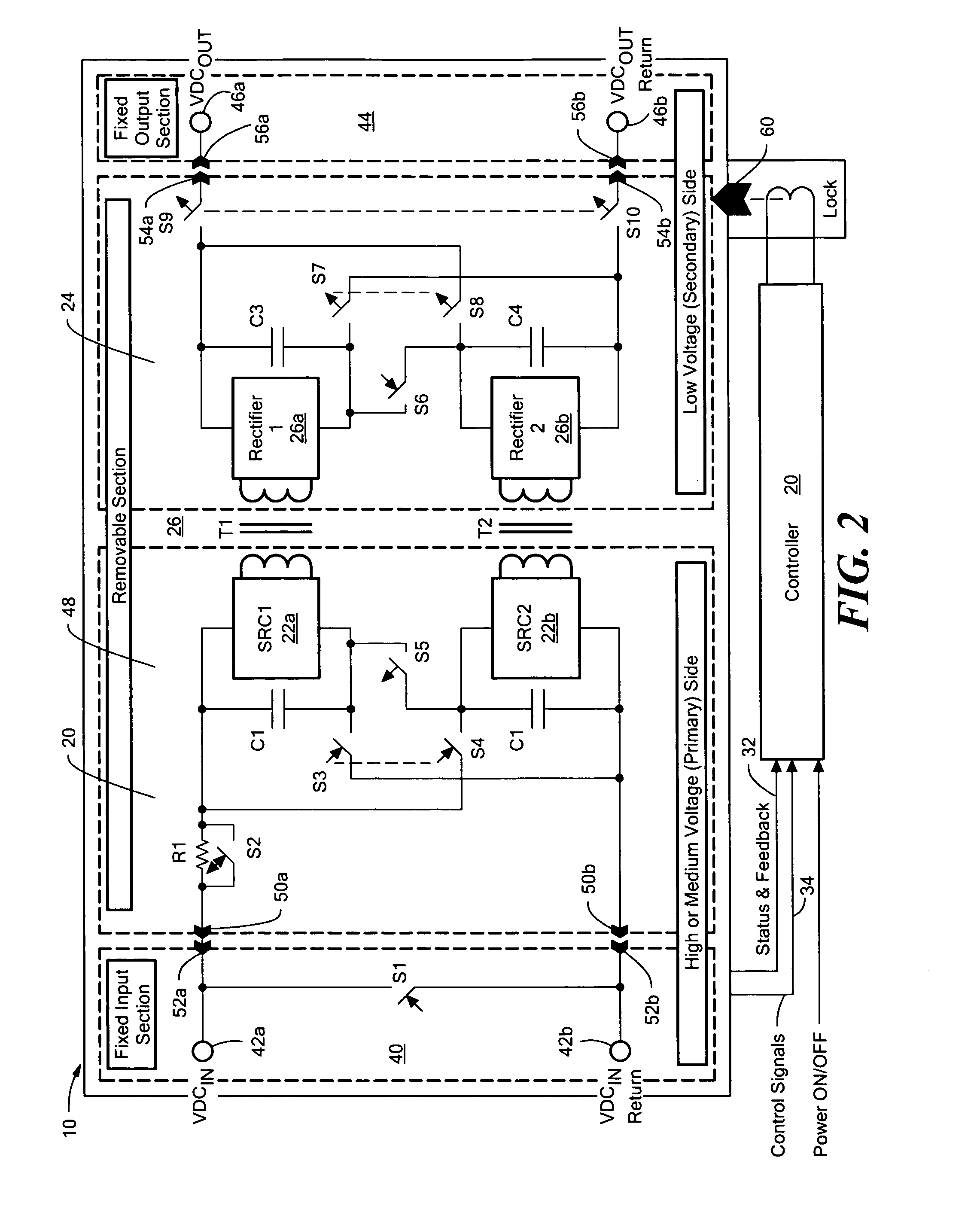
[0011]In some examples, a modular, multi-cell power converter preferably includes a dual-converter cell architecture which enables simple cell reconfiguration in response to a change of operating conditions or a cell failure and, if necessary—safe, simple, and fast isolation and replacement of a failed cell.
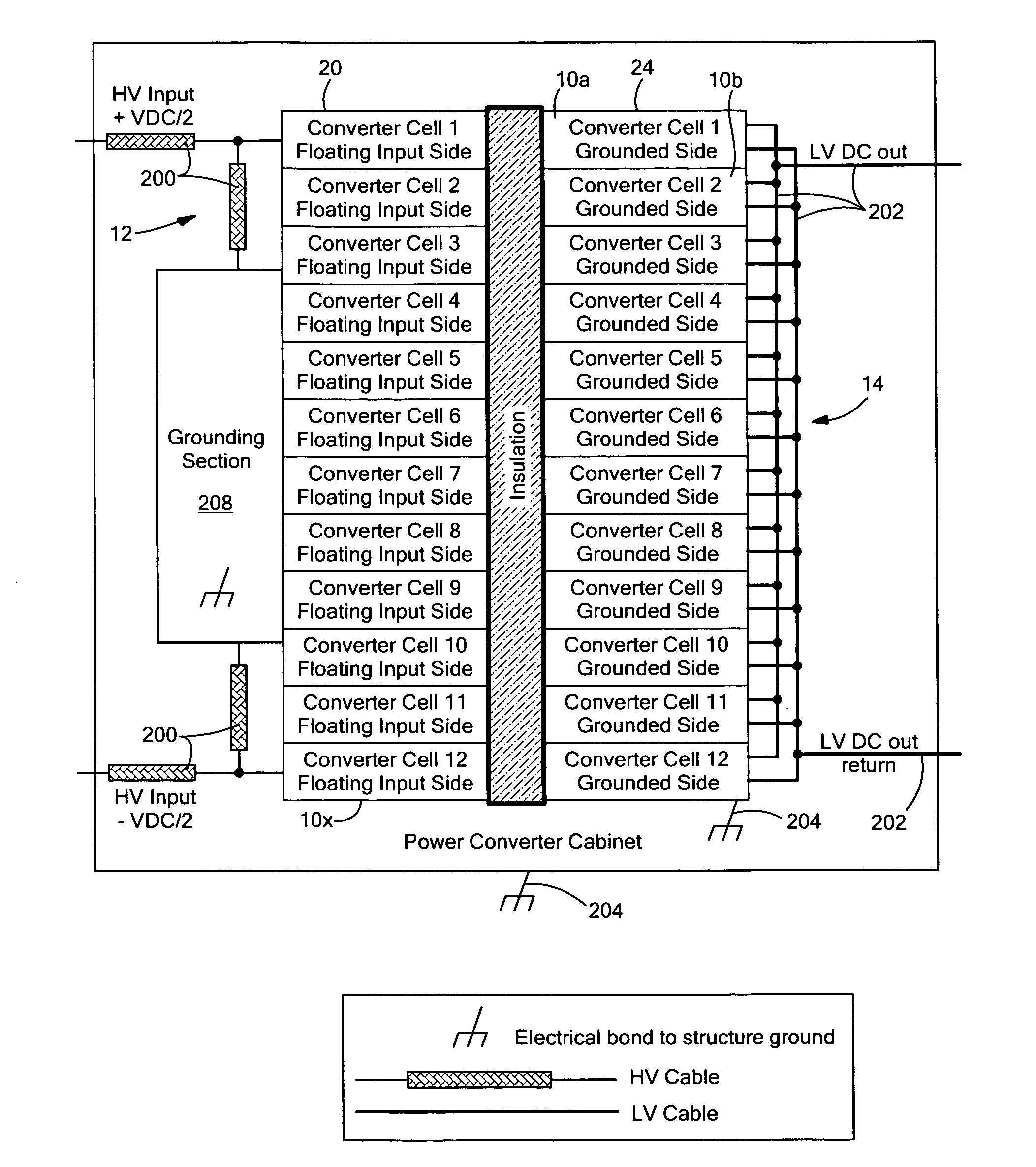
[0013]In one aspect, a modular, multi-cell, high voltage power converter utilizes a stackable mechanical assembly which reduces voltage isolation requirements between the cells and the overall size of the high voltage power converter. Also, dynamic grounding means can be included to reduce voltage stress on series-connected cells in the event of a single or multiple cell failure.
[0014]The subject invention also features, in one aspect, a modular, multi-cell power converter with a specific cell mechanical implementation which includes a fixed input section, a fixed output section, and a removable section. This mechanical implementation aids in safe, simple, and fast removal / replacement of a failed cell without interrupting the converter operation and is especially suitable for converters with series cell connection.

Problems solved by technology

Since series-connected cells share the same current, fault isolation in case of a single or multiple cell failure is difficult.
While the high current condition can be mitigated by shedding non-critical loads, reducing input and output voltage is usually not possible.
The mechanical arrangement of high voltage converter assemblies with replaceable cells presents additional challenges particularly in applications with limited space.
While this approach simplifies multi-module construction and improves assembly flexibility, each cell has to sustain the full bus voltage from the components to the chassis resulting in an increase in size and weight.
While this technique accords simple fault detection and isolation since a ground fault becomes equivalent to a short circuit, it increases current stress for the semiconductors used in the cells.
This method reduces the insulation requirements for the input components thereby allowing more efficient use of space but it does not provide the optimal solution because all of the components on the secondary side have to be insulated from the chassis to sustain 50% of the working voltage.

Method used


Image

  • Reconfigurable multi-cell power converter
  • Reconfigurable multi-cell power converter
  • Reconfigurable multi-cell power converter

Examples


Embodiment Construction

[0030]Aside from the preferred embodiment or embodiments disclosed below, this invention is capable of other embodiments and of being practiced or being carried out in various ways. Thus, it is to be understood that the invention is not limited in its application to the details of construction and the arrangements of components set forth in the following description or illustrated in the drawings. If only one embodiment is described herein, the claims hereof are not to be limited to that embodiment. Moreover, the claims hereof are not to be read restrictively unless there is clear and convincing evidence manifesting a certain exclusion, restriction, or disclaimer.

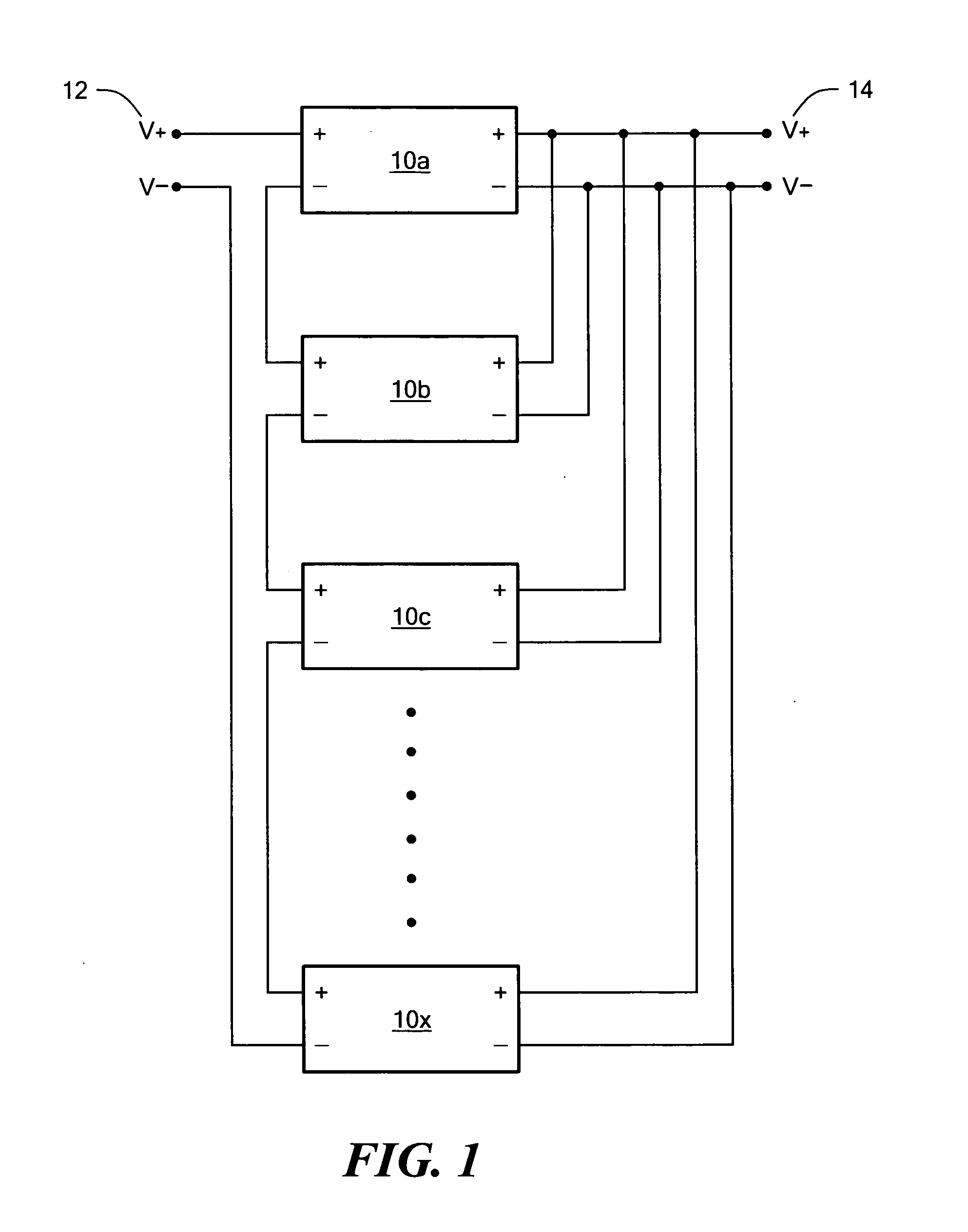
[0031]FIG. 1 shows an example of a reconfigurable multi-cell power converter in accordance with an example of the subject invention. At the converter level, a set of cells 10a-10x are connected between input bus 12 and output bus or load 14 in an input series output parallel (ISOP) configuration (shown) or, alternatively, a...


PUM


Abstract

A reconfigurable multi-cell power converter and method wherein a set of cells are connected between an input bus and a load in an input series output parallel configuration or in an input parallel output series configuration. Each cell includes a primary side reconfigurable between series and parallel operation and a secondary side also reconfigurable between series and parallel operation. Switching circuitry is configured to reconfigure the primary side of each cell between series and parallel operation and vice versa and also to reconfigure the secondary side of each cell between series and parallel operation and vice versa. A controller is configured to actuate the switching circuitry depending a voltage on the input bus and / or cell condition to reconfigure all the cell primary sides and / or secondary sides while maintaining a desired input series output parallel or input parallel output series connection for the set of cells.

Description

RELATED APPLICATIONS[0001]This application hereby claims the benefit of and priority to U.S. Provisional Application Ser. No. 61 / 268,338, filed on Jun. 11, 2009 under 35 U.S.C. §§119, 120, 363, 365, and 37 C.F.R. §1.55 and §1.78.FIELD OF THE INVENTION[0002]The subject invention relates to power converters.BACKGROUND OF THE INVENTION[0003]Power converters are used to convert power from an input bus connected to a power source for a load. Power converters may be designed to convert a fixed AC input voltage into a variable voltage and / or variable frequency output. Other converters are designed to convert an AC input to DC. Still others convert a DC input at one voltage to another voltage. The architecture chosen may provide for high frequency operation, pulse-width-modulation, transformer isolation, and the like. Many power converters include a number of cells also called blocks or modules.[0004]Depending on input and output voltage / current requirements (high voltage, low current or lo...

Claims


Application Information

Patent Timeline
IPC IPC(8): H02J1/00
CPCH02M3/28H02M2001/0074Y10T307/305Y10T307/707H02M1/0074
Inventor JACOBSON, BORIS S.HOLMANSKY, EVGENY N.
Owner RAYTHEON CO
Learn More