
In-line coupling pipe

a coupling pipe and pipe body technology, applied in the field of pipes, can solve the problems of increasing installation costs, requiring additional ground disturbance, and consuming a lot of time, and achieve the effect of effective sealing and convenient installation

Inactive Publication Date: 2010-12-16
KOLBET RANDALL A +1
View PDF16 Cites 3 Cited by
  • Summary
  • Abstract
  • Description
  • Claims
  • Application Information

AI Technical Summary

Benefits of technology

[0018]The primary objective of this invention is to provide a pipe with in-line coupling that can be misaligned yet still provide an effective seal against the leakage of liquid.
[0019]Another objective of this invention is to provide such a pipe that is able to be fabricated using existing technology and easily installed in operative position.

Problems solved by technology

Consequently, construction was extremely time consuming and relatively expensive because of the number of pieces and total weight associated with the components of the drainage system.
This meant that additional ground needed to be disturbed and additional fill needed to be replaced, both of which factors would drive up the cost of installation.
However, this would require additional digging, which of course would be time consuming and drive up the cost of installation.
However, without the ability for the joint to articulate, the use of the pipe for various applications was limited.
One proposed solution to the problem was the manufacture of custom fabricated fittings, bends or joints, however, such structures, depending on the size of pipe involved, could easily cost $1000-2500 per fitting.
Therefore, while in theory a solution to the problem existed, practically speaking the solution was cost prohibitive.
However, even with this improved pipe construction, misalignment of two adjacent segments of pipe could cause leakage and in some cases an undesirable flexing or deformation of the pipe at the juncture of the two joined segments of pipe.
In some cases, such misalignment could be completely accidental and unintended, however in other cases the terrain or curvature associated with the intended path of the pipe could make for a problematic situation.
In these types of situations, existing bell and spigot pipe can typically only permit a slight misalignment on the order of 1° before there is either buckling of the inner wall, or an undesirable deformation of the pipe and the joint, or the pulling out of the gasket from its intended position of providing a seal between the bell and the spigot of directly adjacent pipes.
Any of these undesirable situations can compromise the integrity of the drainage system.

Method used


Image

  • In-line coupling pipe
  • In-line coupling pipe
  • In-line coupling pipe

Examples


Embodiment Construction

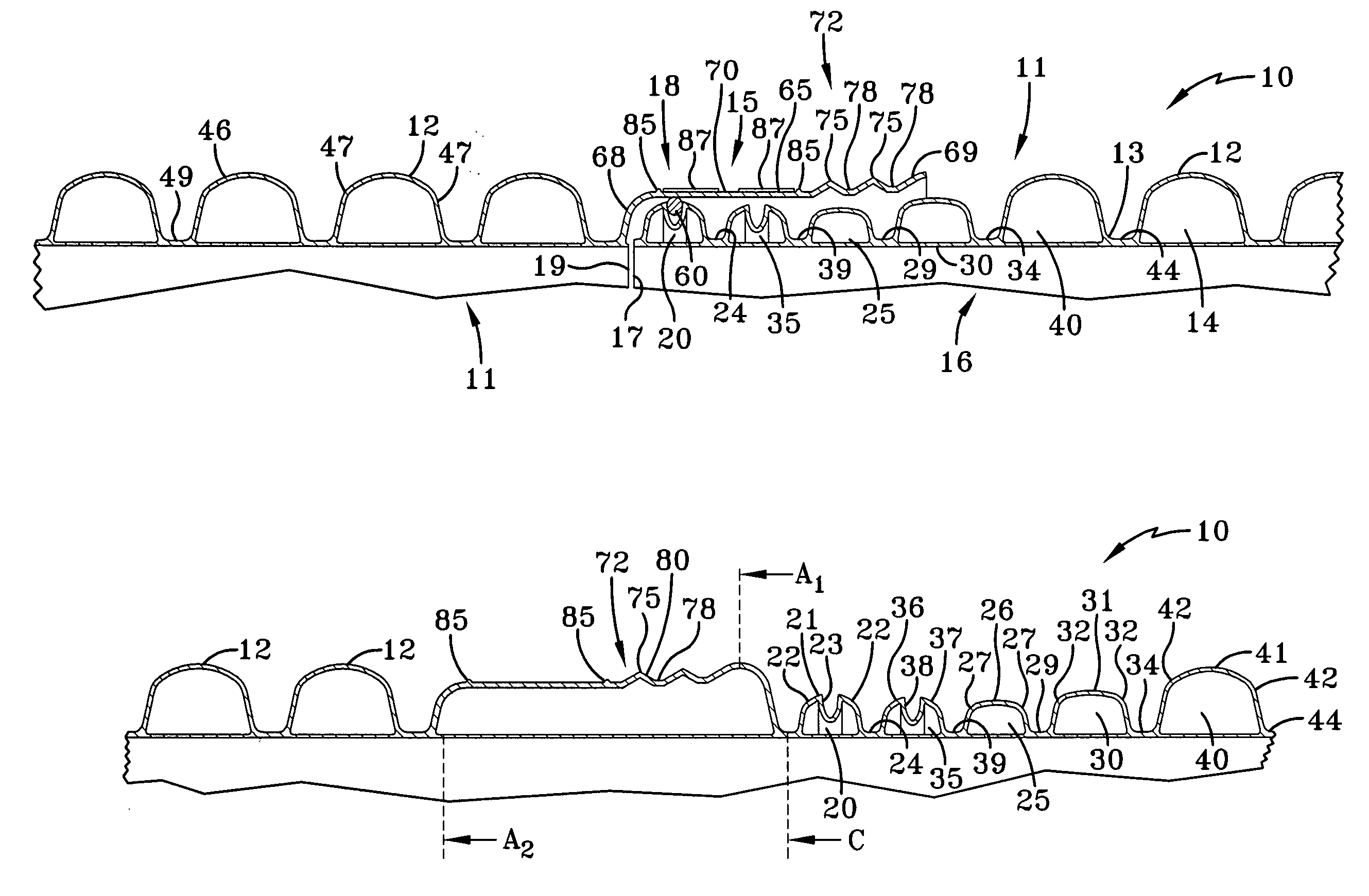
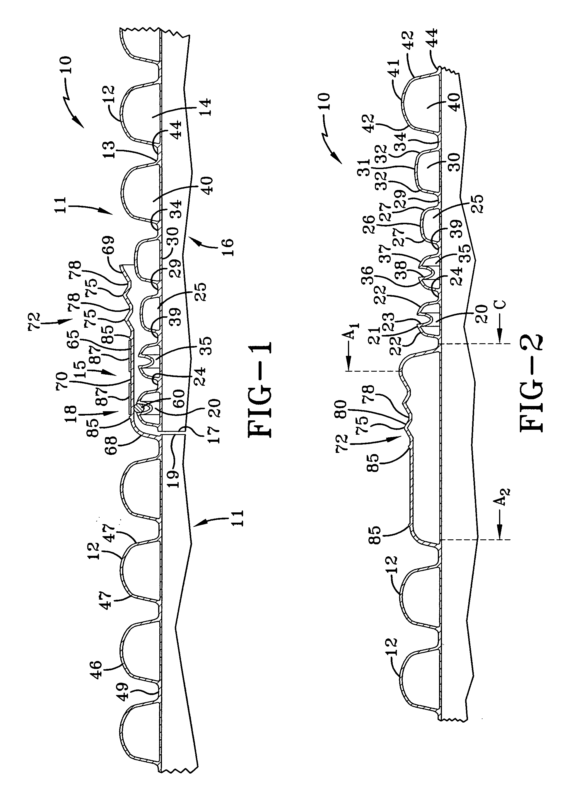
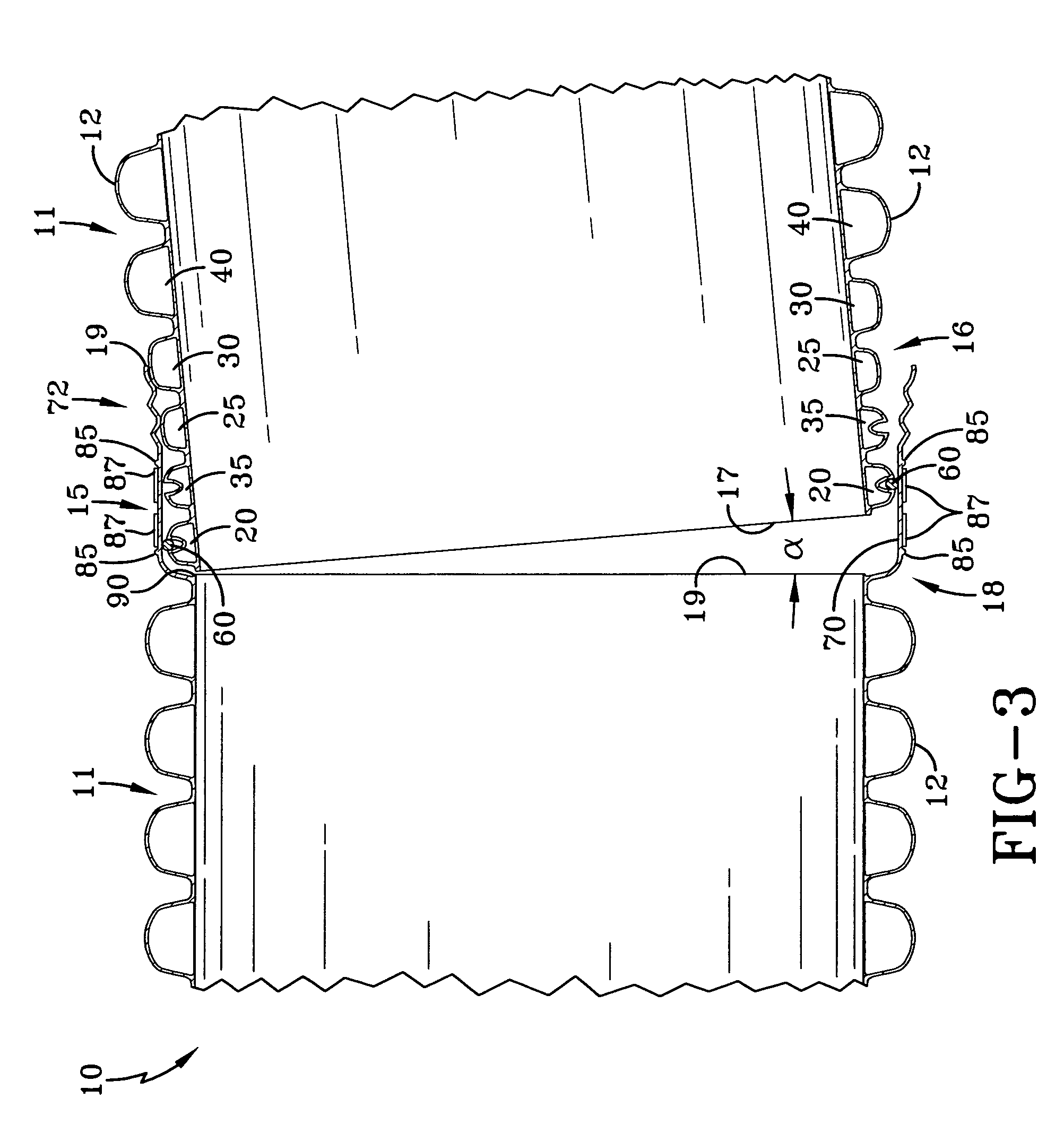
[0025]Having reference to the drawings, attention is directed first to a comparison of FIG. 1 which discloses a corrugated pipe of indeterminate length and FIG. 2 which discloses the extruded product prior to being separated into the individual pipe sections 11 of the pipe designated generally by the numeral 10. The pipe sections 11 can be appreciated as having corrugations 12, with the pipe 10 having an outer wall 13 and an inner wall 14. The invention also features a coupler component 15 having a male portion 16 with a male portion engagement edge 17 and a female portion 18 with a female portion pipe edge 19. The pipe 10 is primarily fabricated from plastic, such as HDPE (high density polyethylene) or other extrudable plastics.

[0026]As can be appreciated from a comparison of FIGS. 1 and 2, the first corrugations 12 are formed having a crest or peak 46, a side wall 47 and a trough 44 directly adjacent the peaks of the first corrugations, with the side walls 47 connecting the first ...


PUM


Abstract

An in-line coupling pipe is provided having a plurality of first corrugations with a male portion at one end of the pipe and a female portion at the other end. The diameter at the crest of the first corrugation being a first distance. The male portion having a second corrugation with the diameter at the crest of the second corrugation being a second distance. The male portion of having a third corrugation intermediate the first corrugation and the second corrugation, with the diameter at the crest of the third corrugation being a third distance. The male portion having a fourth corrugation intermediate the first corrugation and the third corrugation, with the diameter at the crest of the fourth corrugation being a fourth distance, with the first distance being greater than the second or third or fourth distances, the second distance being greater than the third distance, and the fourth distance being greater than second or third distances. The second corrugation has a recess formed therein.

Description

BACKGROUND OF THE INVENTION[0001]1. Field of the Invention[0002]This invention relates generally to pipe, and more particularly to an in-line coupling pipe that allows intentional misalignment of a pipe joint without flexing or deformation of the pipe.[0003]2. Description of the Related Art[0004]This invention is directed to the providing of a pipe of the type used in the drainage of soil for agricultural, commercial, residential, or recreational purposes, including but not limited to sanitary, storm sewer, and agricultural irrigation uses. Historically, concrete, smooth wall plastic and fiberglass pipe were utilized.[0005]In practice, the irrigation, sanitary, or drainage pipe was installed through the placing together of relatively short sections of the pipe to construct the desired drainage, sanitary, or irrigation system. Such sections or pieces would typically be a few feet long. Consequently, construction was extremely time consuming and relatively expensive because of the num...

Claims


Application Information

Patent Timeline
IPC IPC(8): F16D1/00F16L19/00
CPCF16L25/0063F16B2200/10F16L27/02
Inventor KOLBET, RANDALL A.MILLER, KEVIN M.
Owner KOLBET RANDALL A
Learn More