Memory device for a hierarchical memory architecture

a memory device and hierarchical technology, applied in the field of memory devices, can solve the problem of considerable power dissipation at the input/output interfa

Active Publication Date: 2010-12-16
MICRON TECH INC
View PDF5 Cites 126 Cited by
  • Summary
  • Abstract
  • Description
  • Claims
  • Application Information

AI Technical Summary

Problems solved by technology

With current microprocessors the data transaction between the CPU and / or core logic and system memory becomes the bottleneck of system performance.
Due to the intrinsic capacitances of system-level buses, a considerable amount of power may be dissipated at the input / output interface of a processor when binary data is transmitted.

Method used


Image

  • Memory device for a hierarchical memory architecture
  • Memory device for a hierarchical memory architecture
  • Memory device for a hierarchical memory architecture

Examples


Embodiment Construction

[0008]In the following detailed description, numerous specific details are set forth in order to provide a thorough understanding of the invention. However, it will be understood by those skilled in the art that the present invention may be practiced without these specific details. In other instances, well-known methods, procedures, components and circuits have not been described in detail so as not to obscure the present invention.

[0009]It should be understood that the terms “coupled” and “connected”, along with their derivatives, are not intended as synonyms for each other. Rather, in particular embodiments, “connected” may be used to indicate that two or more elements are in direct physical or electrical contact with each other. “Coupled” may be used to indicated that two or more elements are in either direct or indirect (with other intervening elements between them) physical or electrical contact with each other, and / or that the two or more elements co-operate or interact with e...


PUM


Abstract

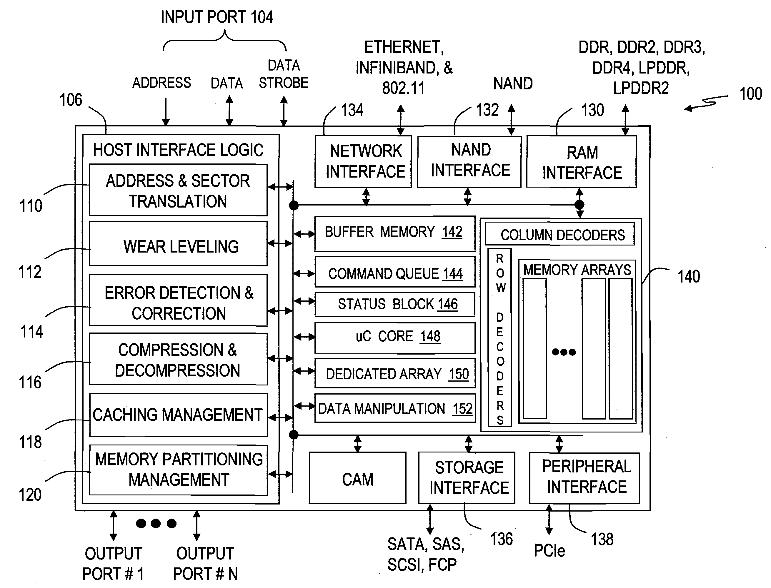
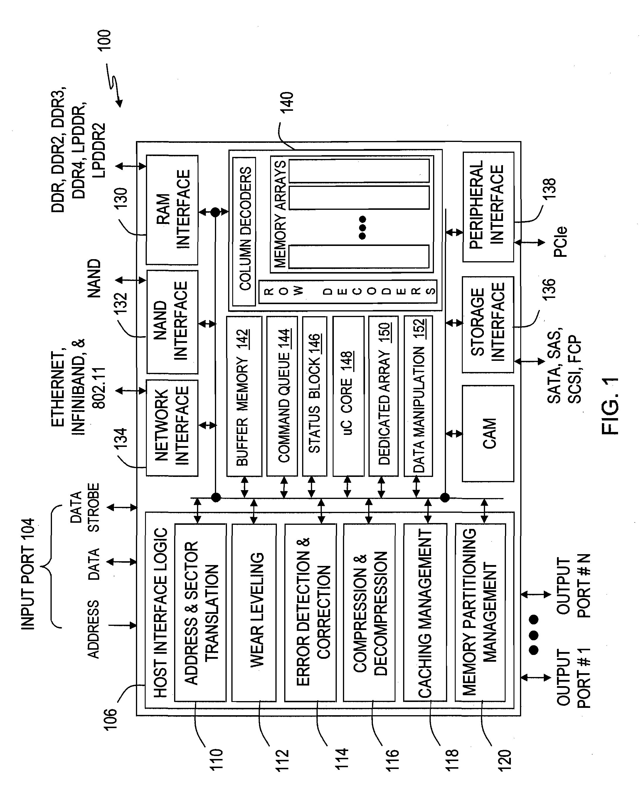
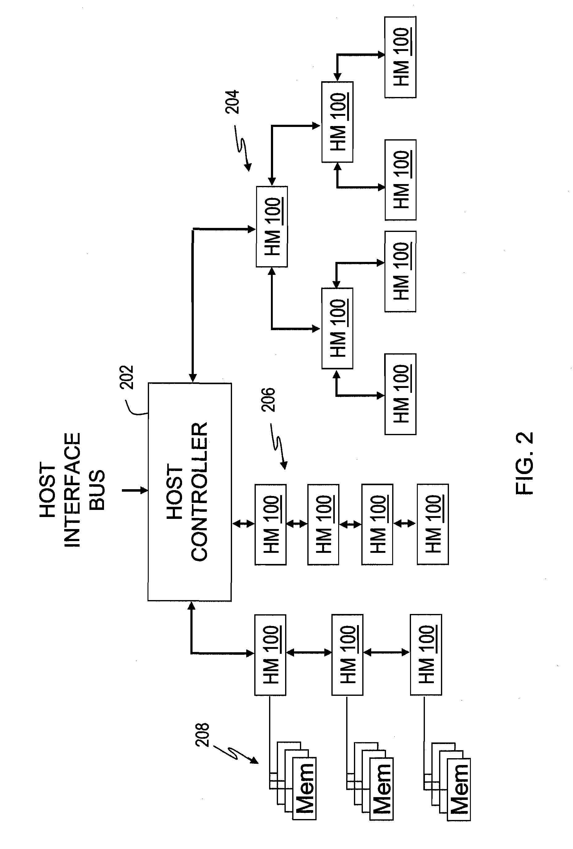
A hierarchical memory device having multiple interfaces with different memory formats includes a Phase Change Memory (PCM). An input port and an output port connect the hierarchical memory device in a daisy-chain hierarchy or a hierarchical tree structure with other memories. Standard non-hierarchical memory devices can also attach to the output port of the hierarchical memory device.

Description

BACKGROUND OF THE INVENTION[0001]With current microprocessors the data transaction between the CPU and / or core logic and system memory becomes the bottleneck of system performance. Due to the intrinsic capacitances of system-level buses, a considerable amount of power may be dissipated at the input / output interface of a processor when binary data is transmitted. Simultaneous power and timing optimization to account for bus latency are critical design constraints taken into account to improve system performance. Additional improvements are needed at the interface to mass-storage memory devices.BRIEF DESCRIPTION OF THE DRAWINGS[0002]The subject matter regarded as the invention is particularly pointed out and distinctly claimed in the concluding portion of the specification. The invention, however, both as to organization and method of operation, together with objects, features, and advantages thereof, may best be understood by reference to the following detailed description when read ...

Claims


Application Information

Patent Timeline
Patent Type & Authority Applications(United States)
IPC IPC(8): G06F12/08G06F12/02G06F12/00G06F13/12
CPCG06F12/0246Y02B60/1225G11C13/0004G06F12/08G06F13/4247Y02D10/00H10N70/231G06F3/0611G06F3/0629G06F3/0688G06F3/06
Inventor EILERT, SEANLEINWANDER, MARK
Owner MICRON TECH INC
Why Eureka
Try Eureka