Drive device for erosion tools

a technology of drive device and tool, which is applied in the direction of manufacturing tools, electrical circuits, electrical-based machining electrodes, etc., can solve the problems of adding materially to manufacturing costs, and achieve the effects of high precision, good rinsing of the bore gap, and high quality of bore formation

Active Publication Date: 2010-12-23
IMM INST FUR MIKROTECHNIK GMBH
View PDF16 Cites 10 Cited by
  • Summary
  • Abstract
  • Description
  • Claims
  • Application Information

AI Technical Summary

Benefits of technology

[0015]An underlying problem of the invention was to devise a drive device for erosion tools which, in order to achieve good rinsing of the bore gap and thereby a high quality of bore formation even at high aspect ratios, combine (superpose) a rotational movement and an axial movement. A further underlying problem was, for such a device, to provide means whereby all movements are executed with high precision, in order to enable use of the device for micromachining. Finally, an underlying problem of the invention was to devise a drive device of the described (inventive) type which is inexpensive to manufacture.

Problems solved by technology

A further underlying problem was, for such a device, to provide means whereby all movements are executed with high precision, in order to enable use of the device for micromachining.
Radial bearings according to the state of the art are in the form of grooved ball bearings which do not have an axial degree of freedom and therefore the superposed axial and radial movements must be decoupled, in a manner which adds materially to manufacturing costs.

Method used


Image

  • Drive device for erosion tools
  • Drive device for erosion tools
  • Drive device for erosion tools

Examples


Embodiment Construction

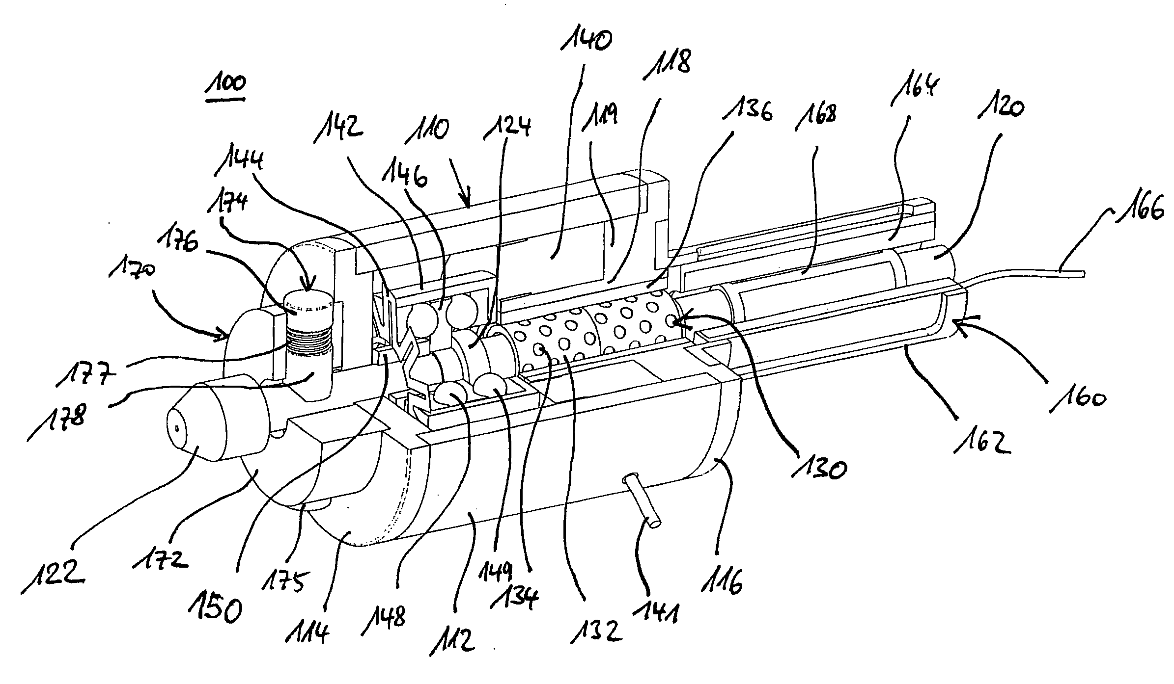
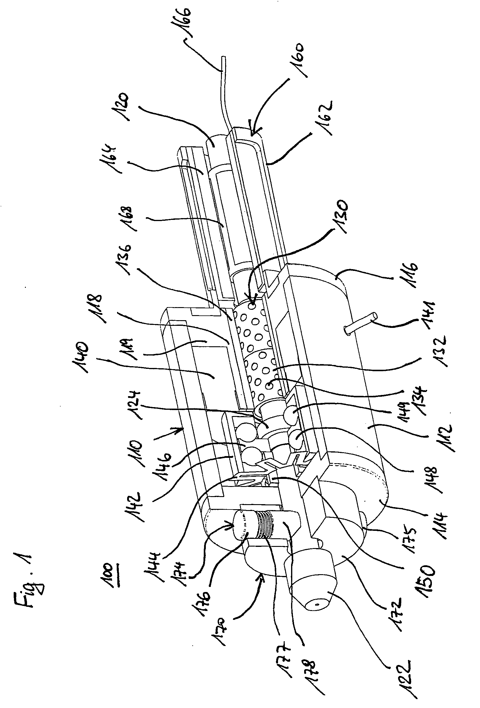
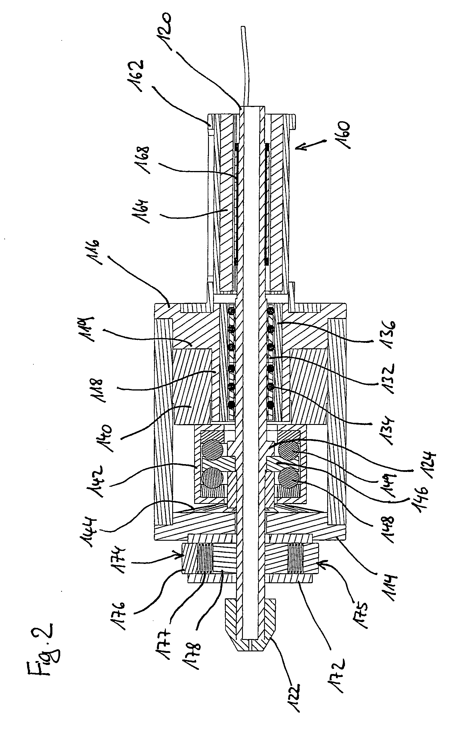
[0050]The drive device 100 illustrated in FIGS. 1 and 2 has a housing 110 with a cylindrical housing shell 112 and two housing covers (114, 116) at respective ends of the housing. A drive shaft 120 is coaxially mounted in the housing 110; shaft 120 exits the housing 110 through the end-disposed housing covers (114, 116). The drive shaft has on one end an electrode accommodating or holding structure 122 in which the eroding electrode (not shown) can be held by compressive force.

[0051]At approximately the axial middle of the shaft, the shaft is radially supported by a ball track 130. The ball track 130 is comprised of a ball race 132 in which a plurality of rows of balls 134 are disposed which rows are distributed around the circumference, said balls being constrained from departing from the race but being allowed to move e.g. rotate relatively freely. The ball race is preferably comprised of plastic so that the balls are retained frictionlessly in the race. The ball track 130 further...


PUM

PropertyMeasurementUnit
internal diameteraaaaaaaaaa
vibration frequencyaaaaaaaaaa

Abstract

A drive device for erosion tools, having a drive shaft, an electrode holder connected to the drive shaft, an axial drive which works on the drive shaft, a rotational drive which works on the drive shaft as a direct drive in a contactless manner, and a radial bearing. The radial bearing is constructed as a ball track.

Description

FIELD OF THE INVENTION[0001]The invention relates to a drive device for eroding tools, particularly for ECM and EDM machining, more specifically for micromachining such as boring of microbores. The drive device has a drive shaft, an electrode holder connected to the drive shaft, an axial drive which acts on the drive shaft, a rotational drive which acts on the drive shaft as a direct drive without contact, and a radial bearing.BACKGROUND OF THE INVENTION[0002]In the area of technology of electroerosive machining, particularly for very small structures (micro-spark erosion), there is the acute problem that high aspect ratios are needed. This means that the required ratio of the structural depth to the (smallest) lateral strain is often very high (10 or more). As the depth of the erosion increases there is the problem that, as a result of decreasing dielectric circulation in the base of the bore, eroded particles tend to accumulate which then impede a defined spark arc-over. This caus...

Claims


Application Information

Patent Timeline
Patent Type & Authority Applications(United States)
IPC IPC(8): B23H1/02
CPCB23H7/18B23H2400/10B23H7/265B23H7/26
Inventor NEUMANN, FRANKLINNEBACH, EGBERTKUNZ, STEFAN
Owner IMM INST FUR MIKROTECHNIK GMBH
Why Eureka
Try Eureka