Method of making antireflective roughened surface and lens barrel with roughened surface made by the method

a technology of anti-reflective roughening and lens barrel, which is applied in the direction of instruments, coatings, optical elements, etc., can solve the problems of interference with the realization of inexpensive products

Active Publication Date: 2010-12-23
PANASONIC CORP
View PDF28 Cites 33 Cited by
  • Summary
  • Abstract
  • Description
  • Claims
  • Application Information

AI Technical Summary

Benefits of technology

[0014]It is therefore an object of the present invention to provide a method of making an antireflective roughened surface, which will hardly reflect incoming light at any of various angles of incidence and which will rarely produce flare or any other optical problem.

Problems solved by technology

However, it is expensive and interferes with realizing an inexpensive product to spray the surface with such a special paint.

Method used


Image

  • Method of making antireflective roughened surface and lens barrel with roughened surface made by the method
  • Method of making antireflective roughened surface and lens barrel with roughened surface made by the method
  • Method of making antireflective roughened surface and lens barrel with roughened surface made by the method

Examples


embodiment 1

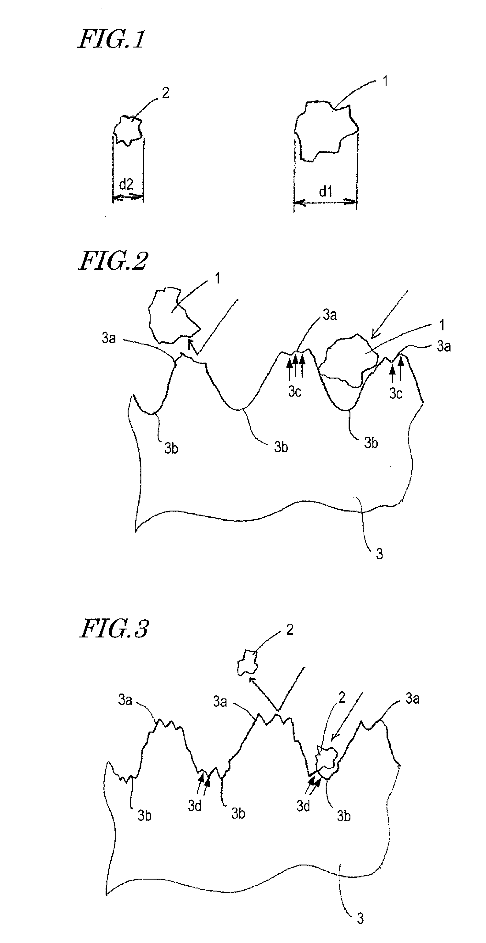
[0043]A First Specific Preferred Embodiment of the present invention to be described below is a method of making a roughened surface by performing different modes of blasting on the same die a number of times compliant with a predetermined standard. As used herein, the “different modes of blasting” means that the blasting is carried out in multiple steps using abrasive grains of different sizes.

[0044]For example, when the blasting is carried out for the first time, a first roughness may be produced using abrasive grains of the biggest size. Next, when the blasting is carried out for the second time, a second roughness may be produced on the first roughness using abrasive grains that are smaller in size than the ones used for the first time around. And if the blasting is further carried out for the third time and on, a third roughness will be produced thereon using even smaller abrasive grains than the ones used last time.

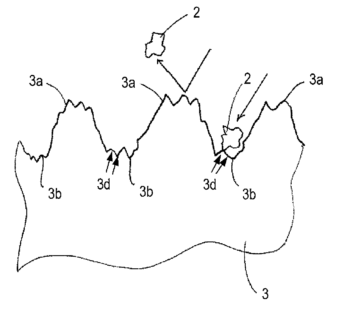
[0045]On the surface of the die thus obtained, the second roug...

embodiment 2

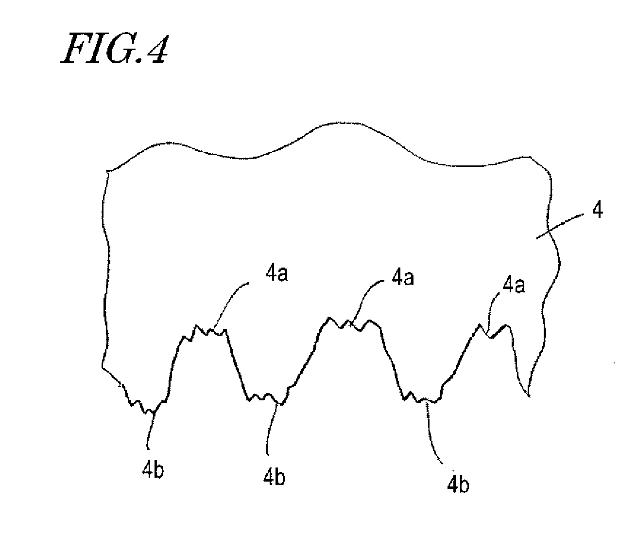
[0062]The molded product 4 obtained in the first preferred embodiment (see FIG. 4) may be used as a part to be put into the lens barrel of an image capture device.

[0063]FIG. 5 is a cross-sectional view illustrating a retractable lens barrel 50 as a second specific preferred embodiment of the present invention. The lens barrel 50 includes multiple lenses L1 to L7, multiple lens holders 51 to 53, an imager 54 and a shielding member 55.

[0064]Inside those lens holders 51 to 53, arranged are resin molded parts 60 to 62 corresponding to the molded product 4 obtained by the method of the first preferred embodiment. On the inner surface of these resin molded parts 60 to 62, there are valleys 4a and mountains 4b as shown in FIG. 4. Thus, it is possible to prevent unnecessary portions of the externally incoming light that have also entered this lens barrel 50 through the lenses L1 and L2 but will not be guided to the imager 54 from being reflected internally by the lens barrel 50. It should b...


PUM

PropertyMeasurementUnit
sizeaaaaaaaaaa
sizeaaaaaaaaaa
sizeaaaaaaaaaa

Abstract

A method of turning the surface of a die, which is used to make a product, into an antireflective roughened one includes the steps of: a) producing a first roughness on the surface of the die; and b) producing a second roughness, which is smaller than the first roughness, on the surface of the die on which the first roughness has already been produced.

Description

BACKGROUND OF THE INVENTION[0001]1. Field of the Invention[0002]The present invention relates to a method of turning the surface of a die, which is used to make a part to put into the lens barrel of a camera, for example, into an antireflective roughened one.[0003]2. Description of the Related Art[0004]A camera such as a still camera or a camcorder receives external light, produces a subject image using an optical system inside its lens barrel, and then projects the subject image onto an image capturing member such as a photosensitive film or an image capture device. In this case, only the subject image that has been produced by the optical system is preferably incident on the image capturing member. Actually, however, there is also other light that has been reflected from inside the lens barrel before impinging on the image capturing member. Such unnecessary reflected light will be superposed as “flare” on the subject image. It is preferred that no flare be produced unless it is us...

Claims


Application Information

Patent Timeline
Patent Type & Authority Applications(United States)
IPC IPC(8): G02B5/02B24C1/06
CPCB24C1/08G02B27/0018G02B1/118B24C1/00G02B1/11
Inventor HIRABAYASHI, KOICHIROUNO, TETSUYABOKU, KAZUTAKEKAWAMURA, TAKAYUKI
Owner PANASONIC CORP
Why Eureka
Try Eureka