
Kort nozzle

a kort nozzle and nozzle technology, applied in the direction of water-acting propulsive elements, propulsive elements, vessel construction, etc., can solve the problems of considerable vibrations which can be transmitted to the hull of the ship, disadvantageous effect, and inability to achieve the effect of kort nozzles

Inactive Publication Date: 2010-12-23
BECKER MARINE SYST
View PDF7 Cites 0 Cited by
  • Summary
  • Abstract
  • Description
  • Claims
  • Application Information

AI Technical Summary

Benefits of technology

The invention provides a Kort nozzle with a nozzle ring that has openings in the walls to create a laminar flow of sea water or salt water from outside the nozzle to inside the nozzle. The openings are placed in two central areas of the nozzle ring to avoid or reduce swirl or recirculation formation. The openings are designed to create an optimal effect and suppress swirl or recirculation formation as much as possible. The nozzle ring is made of one-piece and has a monolithic wall with openings in both central areas. The openings are always open and water flows through both openings continuously throughout the operation of the Kort nozzle. This ensures that the outside-in flow of water is provided for in all situations of operation where needed.

Problems solved by technology

These recirculations or swirls have a disadvantageous effect on the power of the Kort nozzle.
Since the recirculations occur only in a locally limited side area and the flow runs substantially laminarly in the other areas as usual, considerable vibrations which can be transmitted to the hull of the ship and which have also a disadvantageous effect occur.
Therefore, the disadvantages described above occur.

Method used


Image

  • Kort nozzle
  • Kort nozzle
  • Kort nozzle

Examples


Embodiment Construction

[0037]For the different embodiments represented below, the same components are provided with the same reference numerals.

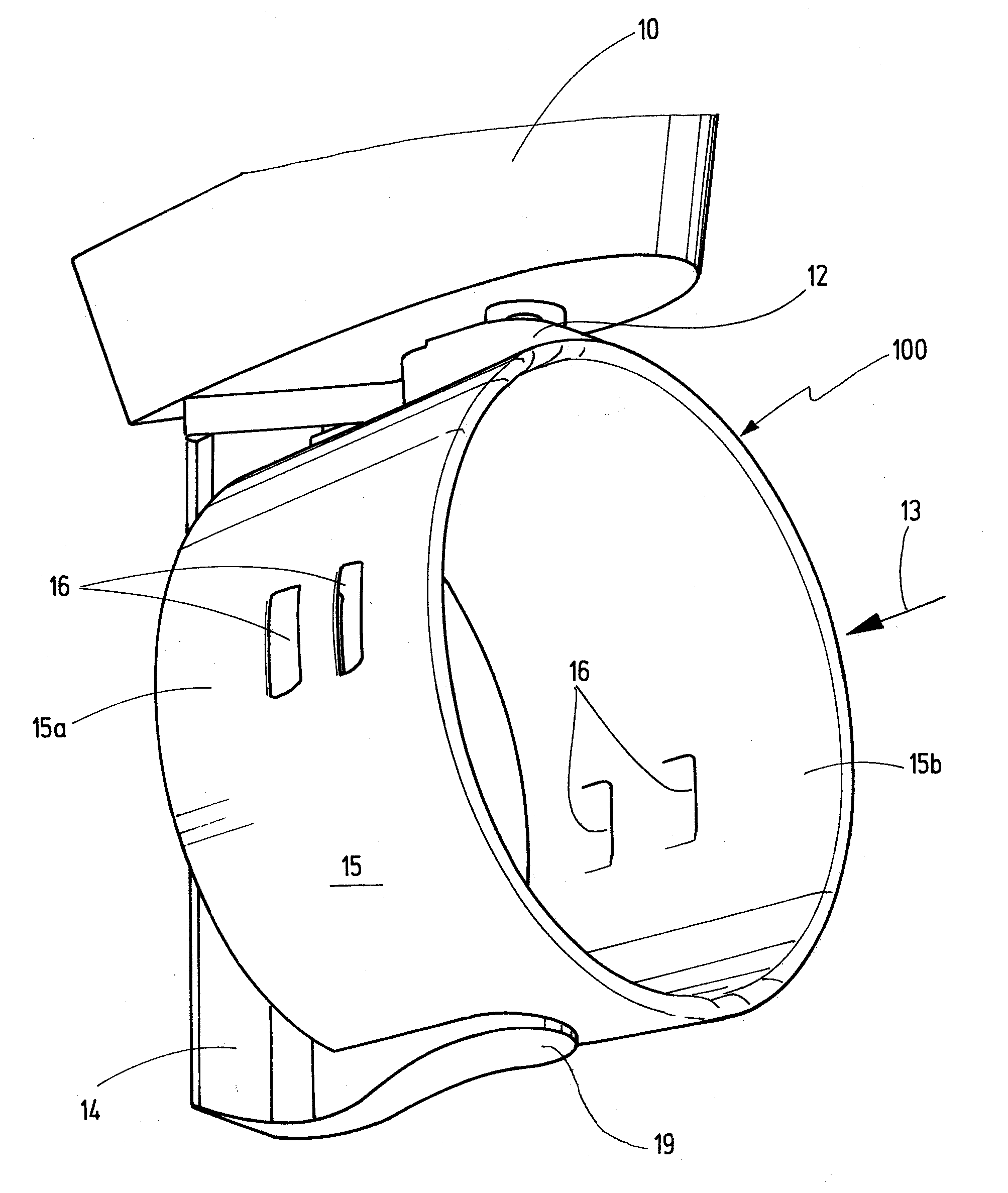
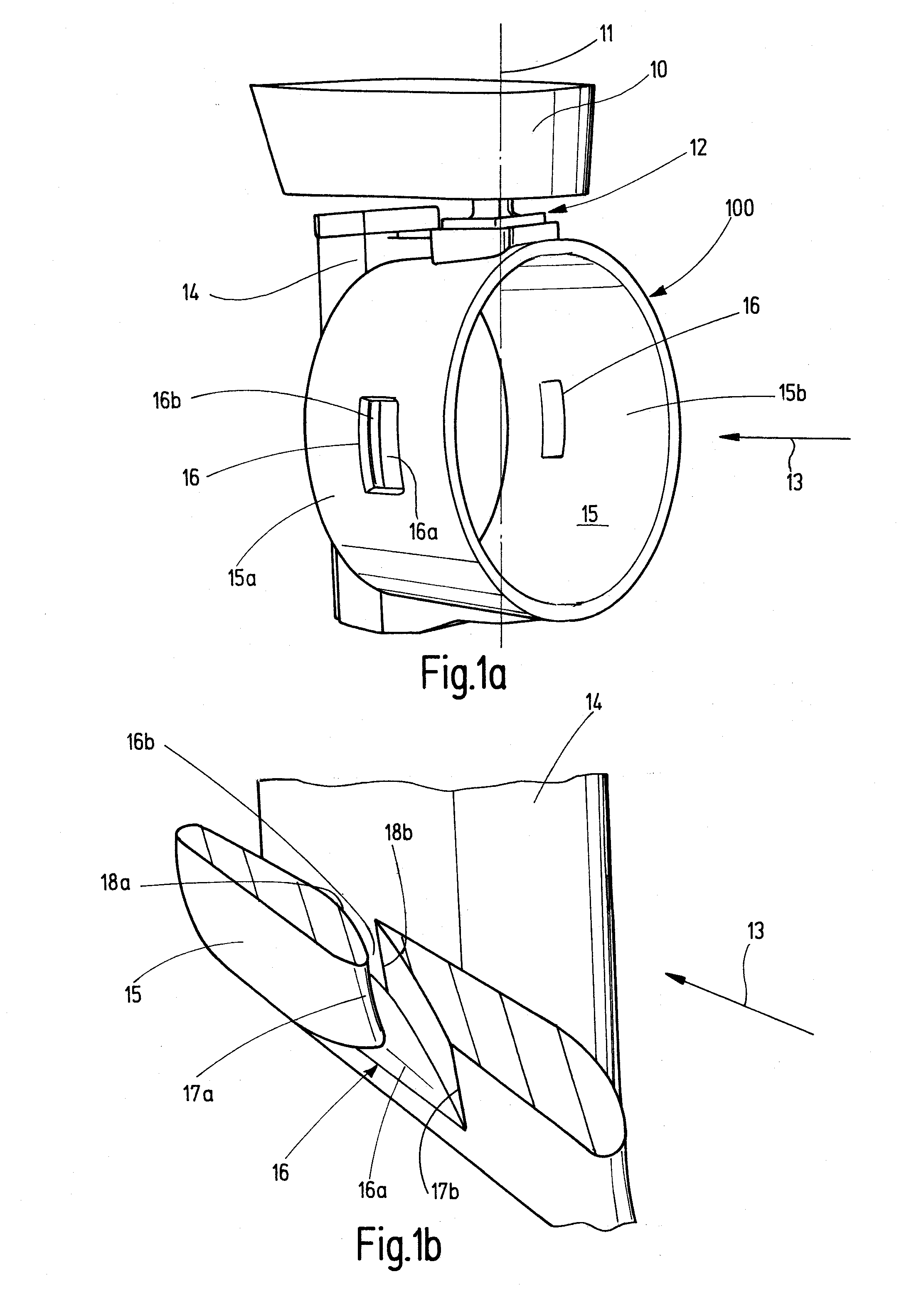
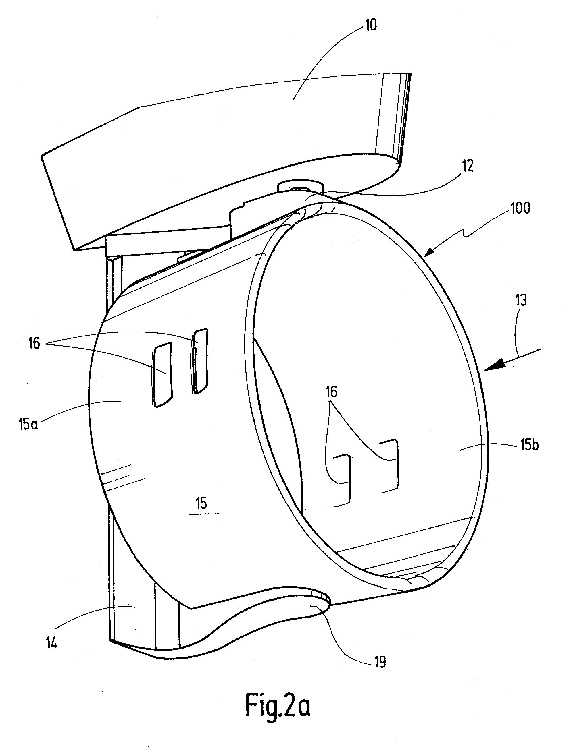
[0038]FIG. 1a shows a perspective view of a Kort nozzle 100 which is positioned swivelable on the hull 10 of a ship. The hull 10 of a ship is depicted only partially for reasons of clarity. The Kort nozzle is connected with the hull 10 by means of a bearing 12 and is rotatable about the rudder axis 11. The rudder axis 11 corresponds to the vertical axis. The Kort nozzle 100 is furthermore connected with the hull in its lower area by a further bearing (not represented here). Considering the flow direction 13, a movable or controllable flap 14 follows at the end of the Kort nozzle 100. The Kort nozzle 100 comprises a ring-shaped configured nozzle ring 15 which is configured conically and which tapers in the flow direction 13 and which forms the wall of the Kort nozzle 100. An opening 16 is placed respectively in each central side areas 15a, 15b of the nozzle ring 15...


PUM


Abstract

In order to indicate a Kort nozzle configured rotatable around the rudder axis of a ship, for which the occurrence of recirculations or of swirls is avoided or reduced even with an angular position with respect to a longitudinal axis of the ship and a globally uniform flow pattern adjusts as far as possible, at least one opening is provided in each of two central areas of a nozzle ring enveloping a ship's propeller.

Description

FIELD OF THE INVENTION[0001]This invention relates to a Kort nozzle which is configured rotatable about the rudder axis of a ship.BACKGROUND OF THE INVENTION[0002]A Kort nozzle is a conically tapered tube or duct in which the propeller of a ship is placed. The tube is a so-called nozzle ring and forms the wall of the Kort nozzle. Due to the taper of the nozzle ring towards the stern of the ship, the Kort nozzles can transmit an additional thrust to the ship without the output having to be increased. Besides the propulsion improving properties of the Kort nozzle, pitching by rough sea is thus reduced so that by sea disturbance the lost of velocity can be reduced and the directional stability can be increased. Since the inherent resistance of the Kort nozzle increases approximately quadratically as the speed of the ship increases, its advantages are effective in particular for slow ships which have a big propeller thrust (for example tugboats, fishing vehicles, etc.).[0003]Besides fix...

Claims


Application Information

Patent Timeline
Patent Type & Authority Applications(United States)
IPC IPC(8): B63H5/15
CPCB63H5/14B63H25/46B63H25/42B63H5/16
Inventor KLUGE, MATHIAS
Owner BECKER MARINE SYST
Learn More