Agricultural sprayer valve unit and agricultural sprayer valve device

Pending Publication Date: 2021-06-03
SCHULTE REINHOLD
View PDF0 Cites 0 Cited by
  • Summary
  • Abstract
  • Description
  • Claims
  • Application Information

AI Technical Summary

Benefits of technology

[0042]It is possible that the control logic is designed such that the parameter is determined from a local maximum of the electric bias (so the current or the voltage) during the OFF-phase of the pulse-width modulation or the closing movement of the electronically controlled control valve. It has surprisingly shown that during the closing movement of the electronically controlled control valve a change of the flow rate and / or of the extent of the clogging a local maximum of this type changes its position and / or its absolute value which allows a simple and at the same time reliable determination of the parameter.
[0047]In the case that an agricultural sprayer valve device comprises a plurality of agricultural sprayer valve units which might e. g. be arranged with an offset on a spraying boom it is proposed that for testing purposes or referencing purposes the control valves of the agricultural sprayer valve unit are not transferred at the same time into their closing positions, but with an offset in time. It is e. g. possible that the agricultural sprayer valve units are each separately and with an offset in time controlled into the closed position. However, it is also possible that in a subgroup of the agricultural sprayer valve units the agricultural sprayer valve units of this subgroup are simultaneously controlled into the closed position. Then with an offset in time agricultural sprayer valve units of at least one other subgroup are controlled into the closed position. This embodiment in particular leads to the advantage that when executing the test operation during the drive over a field the output behavior is not effected at the same time and with an increased extent, but only locally and with an offset in time. It is also possible that due to the offset in time the occurrence of pressure oscillations in the fluidic supply system can be avoided or reduced.
[0053]It is possible that for a given extent of the clogging of the agricultural sprayer valve unit the electric bias is independent on the pressure in the primary line or there is only a tolerable pressure dependency. When this is not the case the invention proposes that a referencing operation for one agricultural sprayer valve unit is executed for different pressures in the primary line. In this case then a plurality of pressure-dependent referencing biases can be stored. An extent of a clogging of the agricultural sprayer valve unit, of the secondary line and / or an output nozzle can in this case be determined by a comparison of the referencing bias for the pressure which biases the primary line in the testing operation with the electric bias sensed during the testing operation. In this way, it is possible to further increase the precision and the reliability of the determination of the extent of a clogging.
[0054]Another embodiment of the invention aims for the reduction of the power consumption of the agricultural sprayer valve unit: Whereas it is generally assumed that a permanent energization of the holding magnet with a sufficient holding current is required for maintaining the closed position of the holding magnet, the invention proposes that by means of a control logic of a control unit the electric bias (in particular the voltage applied to the holding magnet) is varied in the closed position of the control valve in an oscillating fashion between a minimum and a maximum. Here, any oscillating curve of the electric bias between the maximum and the minimum is possible. Preferably an oscillating square or rectangular voltage oscillating between a maximum and a minimum of zero is applied to the holding magnet. It has surprisingly shown that despite of a temporary reduction of the electric bias from the maximum to the minimum the holding magnet and therewith the agricultural sprayer valve unit maintains its closed position. The following effects (which are not intended to limit the invention) might be responsible for such behavior:
[0061]The reference signs contained in the claims are not limiting the extent of the matter protected by the claims. Their sole function is to make the claims easier to understand.

Problems solved by technology

Here, the overflow valve is a passive overflow valve so that it is not possible to change the valve position by an electronic energization and / or the valve position of the overflow valve only depends on the effective fluidic pressures and any springs biasing the overflow valve.

Method used


Image

  • Agricultural sprayer valve unit and agricultural sprayer valve device
  • Agricultural sprayer valve unit and agricultural sprayer valve device
  • Agricultural sprayer valve unit and agricultural sprayer valve device

Examples


Embodiment Construction

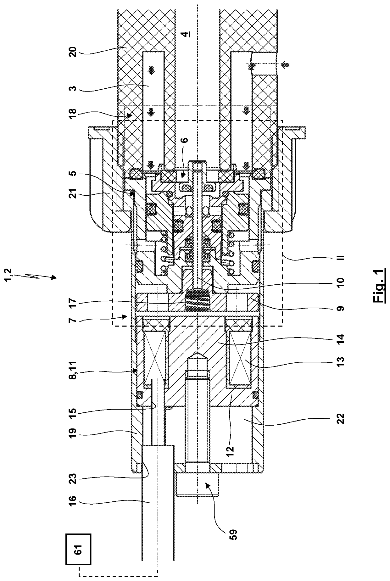
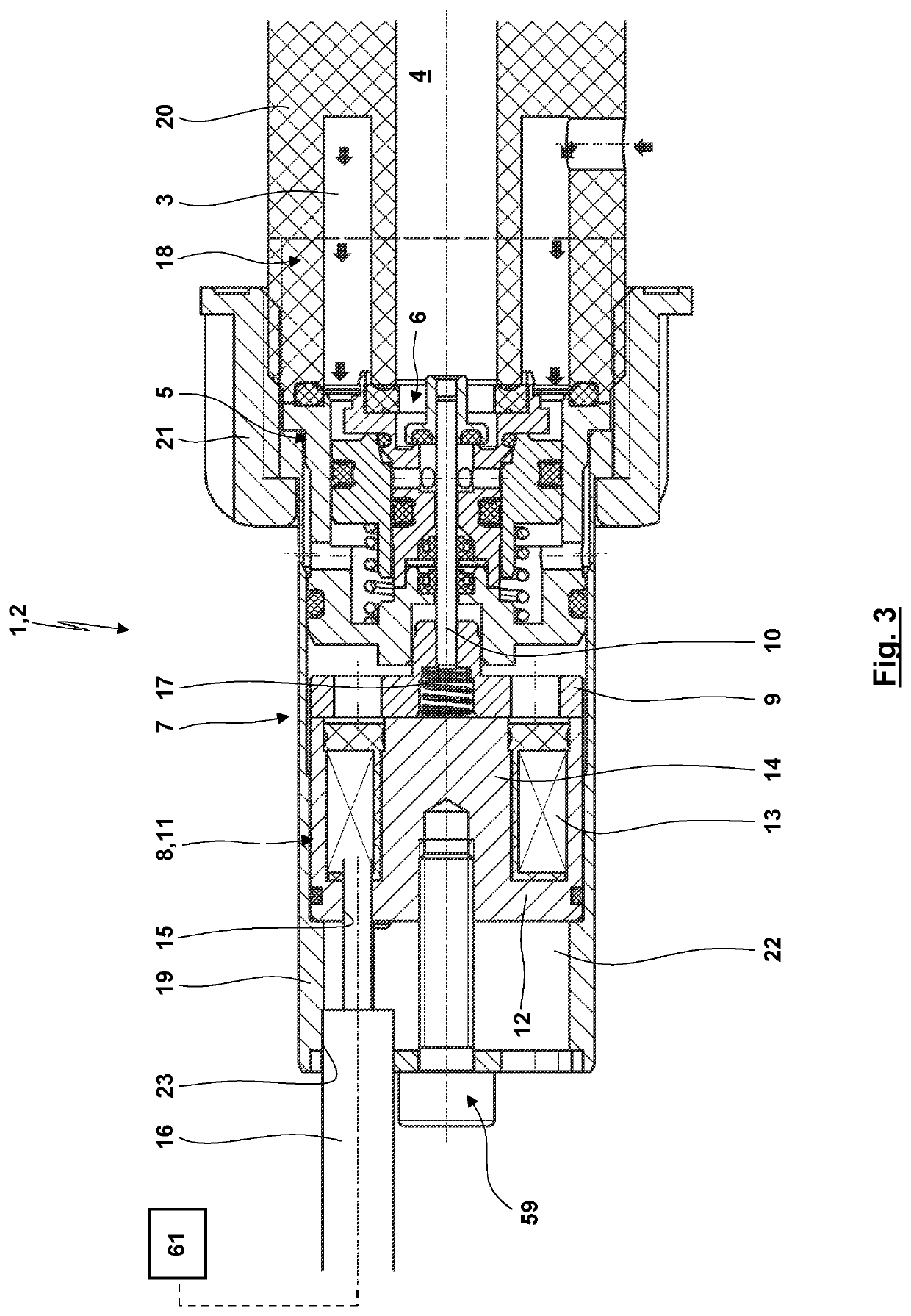
[0072]FIG. 1 in a longitudinal sectional view shows an agricultural sprayer valve unit 1 which might constitute an agricultural sprayer valve device 2 or might be a component of the same.

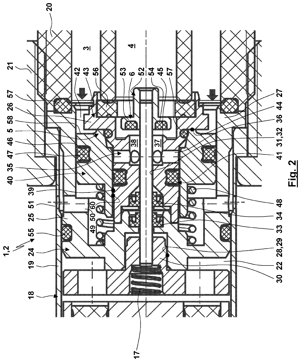
[0073]The agricultural sprayer valve unit 1 comprises a port on the inlet side (not shown here) which leads to a primary line 3 and a port arranged on the outlet side (not being shown here) which leads to a secondary line 4. The primary line 3 is connected via an overflow valve 5 and an electronically controlled control valve 6 to the secondary line 4. Here, the primary line 3, the overflow valve 5, the control valve 6 and the secondary line 4 are arranged in a fluidic series connection in this order.

[0074]The electronic actuation of the control valve 6 is provided by an electric actuator 7 which comprises a holding magnet 8 for the shown embodiment. The holding magnet 8 biases an armature 9 which carries a valve stem 10. The holding magnet 8 is here embodied as a pot magnet 11. For that purpose, th...


PUM


Abstract

The invention relates to an agricultural sprayer valve unit. An electronically controlled control valve and a passive overflow valve serially connected in fluid communication are arranged in the agricultural sprayer valve unit between a primary line and a secondary line. The agricultural sprayer valve unit may be used for any agricultural sprayer valve device, in particular in connection with the discharge of a fluid such as water, a fertilizer, an insecticide, a weedkiller and the like in agricultural or fruit or vegetable cultivation.

Description

CROSS REFERENCE TO RELATED APPLICATIONS[0001]This application is a continuation of International Application PCT / EP2019 / 071573 with an international filing date of Aug. 12, 2019 and claiming priority to European Patent Application No. EP 18 189 451.0 entitled “Agricultural Spraying Valve Unit and Agricultural Straying Valve Device”, filed on Aug. 17, 2018.FIELD OF THE INVENTION[0002]The present invention relates to a valve unit for an agricultural sprayer (in the following “agricultural sprayer valve unit”) and a valve device for an agricultural sprayer (in the following “agricultural sprayer valve device”) comprising an agricultural sprayer valve unit of that type.[0003]Agricultural sprayer valve units and agricultural sprayer valve devices serve for controlling (open-loop control or closed-loop control, both subsumed under “control” within the frame of the present invention) the output of a fluid by means of an agricultural sprayer of any construction and any intended use. An agri...

Claims


Application Information

Patent Timeline
Patent Type & Authority Applications(United States)
IPC IPC(8): B05B12/08B05B12/00B05B12/02F16K17/04F16K31/06G05D7/00B05B1/20
CPCB05B12/087B05B12/004B05B12/02B05B1/20F16K31/0655G05D7/005F16K17/048F16K31/06F16K17/04B05B12/08A01M7/00
Inventor SCHULTE, REINHOLD
Owner SCHULTE REINHOLD
Why Eureka
Try Eureka