Samara wing

Inactive Publication Date: 2010-12-23
CHARLES STARK DRAPER LABORATORY
View PDF9 Cites 9 Cited by
  • Summary
  • Abstract
  • Description
  • Claims
  • Application Information

AI Technical Summary

Benefits of technology

[0011]It is a further object of this invention to provide such a samara wing which enables a more accurate drop point.
[0012]It is a further object of this invention to provide such a samara wing which is easy to deploy.

Problems solved by technology

Also, winds aloft can adversely affect the accuracy of the desired drop point when the samara wing begins autorotating at high altitudes.
It is difficult to design a single wing that has both pitch stability and pitch trim.
The problem of designing a samara is very similar to the problem of designing a flying wing.
This results in a nose-down moment.
A second problem could be called “control ambiguity.” The conventional way to increase the lift on a wing is to have a flap at the trailing edge that deflects downward.
However, the lift will only increase if the angle of attack of the main part (the unflapped part) of the wing remains fixed.

Method used


Image

  • Samara wing
  • Samara wing
  • Samara wing

Examples


Embodiment Construction

[0031]Aside from the preferred embodiment or embodiments disclosed below, this invention is capable of other embodiments and of being practiced or being carried out in various ways. Thus, it is to be understood that the invention is not limited in its application to the details of construction and the arrangements of components set forth in the following description or illustrated in the drawings. If only one embodiment is described herein, the claims hereof are not to be limited to that embodiment. Moreover, the claims hereof are not to be read restrictively unless there is clear and convincing evidence manifesting a certain exclusion, restriction, or disclaimer.

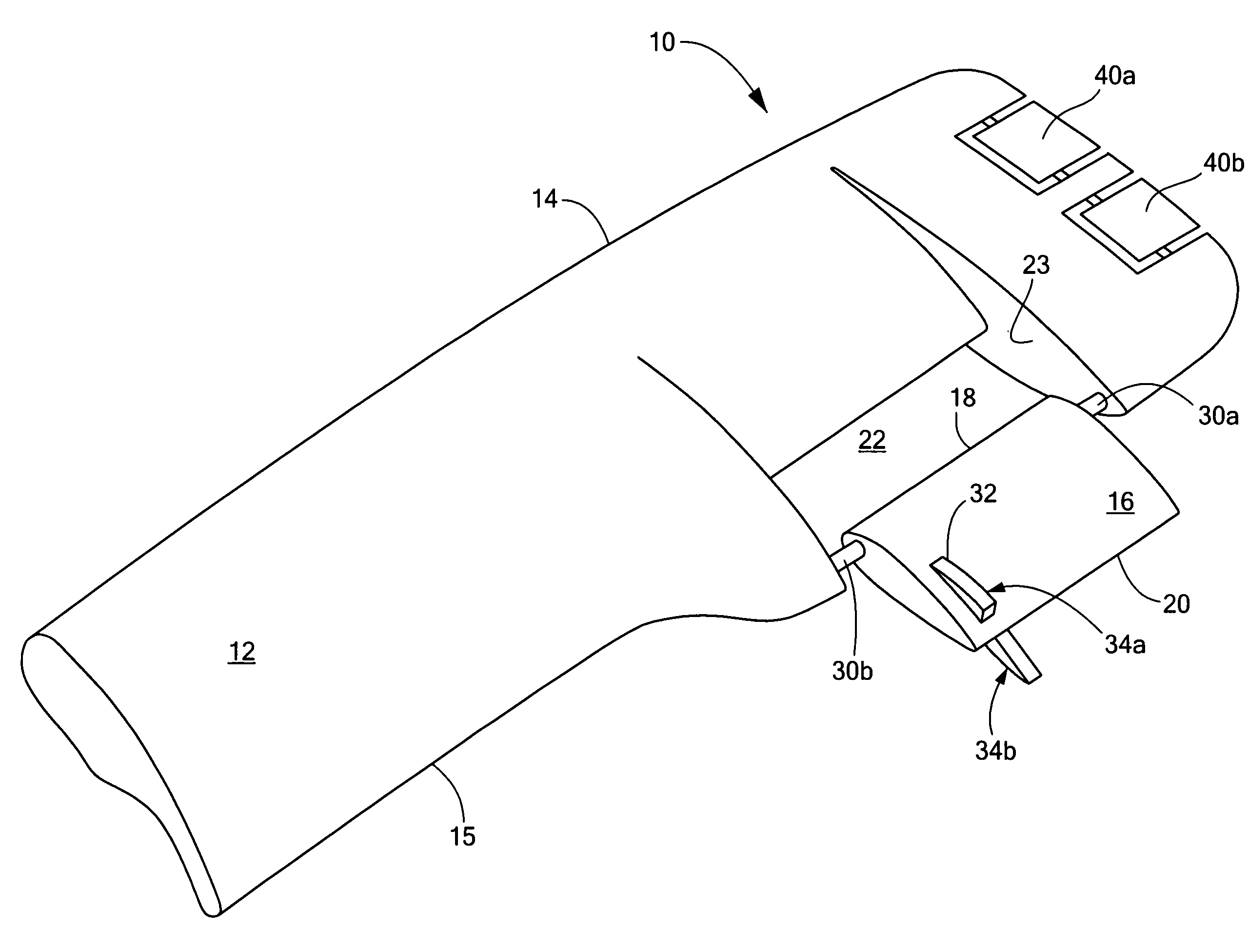
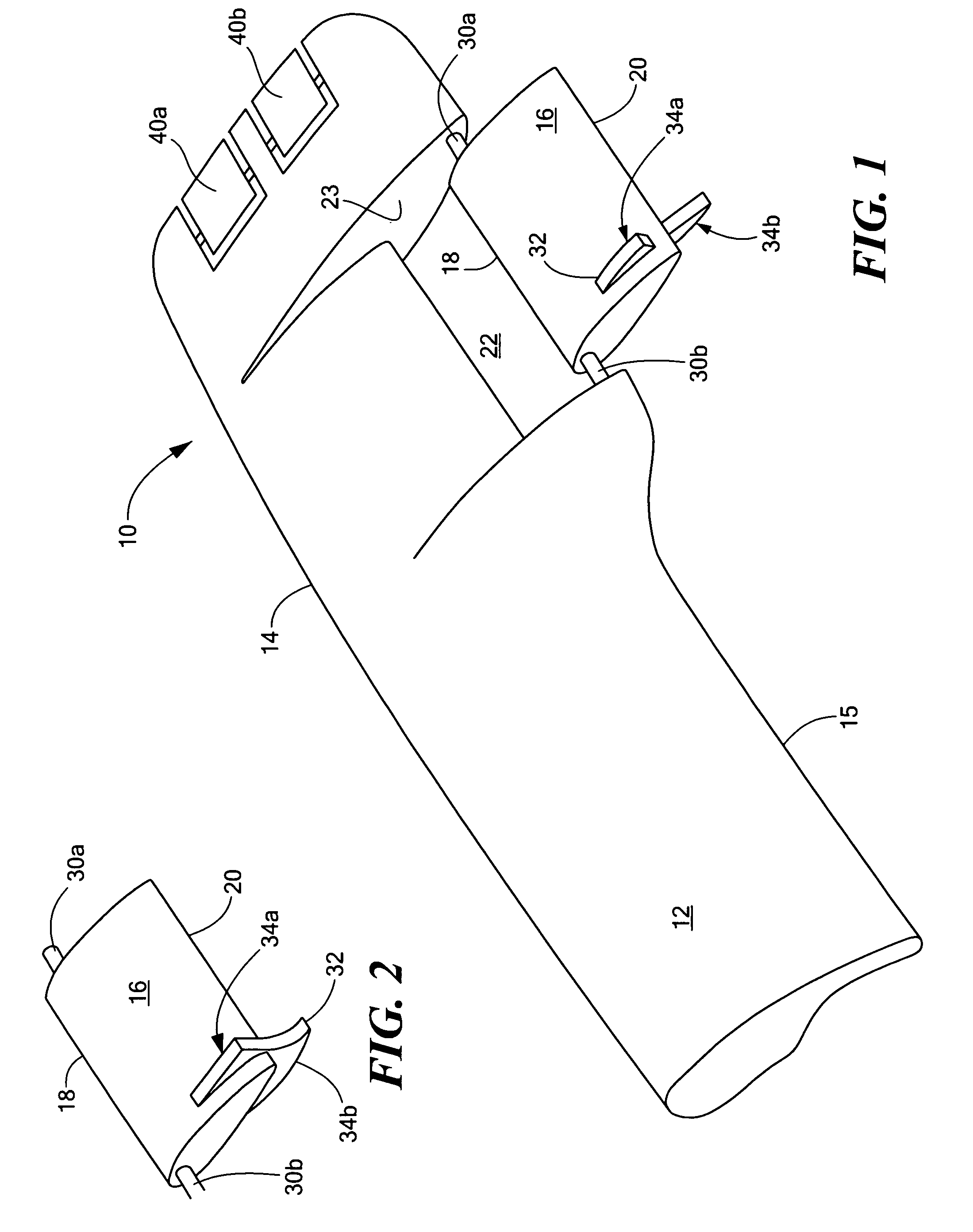
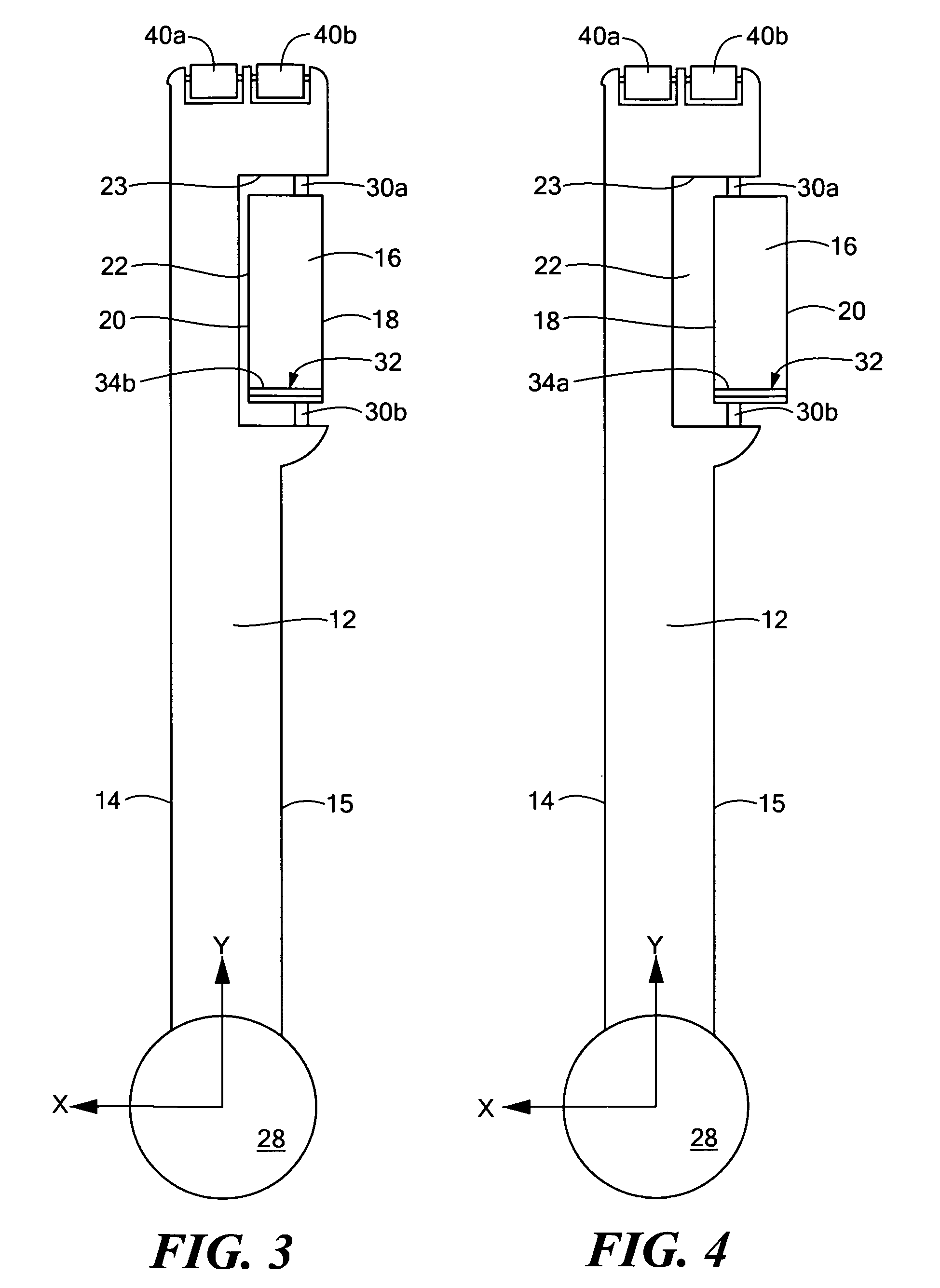
[0032]FIG. 1 shows samara wing 10 in accordance with one example of the subject invention. Main wing 12 includes leading edge 14 and trailing edge 15. Main wing 12 may be any desired airfoil shape known in the art. Main wing 12 may be composite in construction (e.g., a foam core covered with fibers in a resin matrix or any ...


PUM


Abstract

A samara wing including a main wing with a leading edge and a trailing edge. An aileron has a leading edge and a trailing edge and is pivotally attached proximate the trailing edge of the main wing and separated therefrom by a gap. The aileron is rotatable between the first position where the trailing edge of the aileron is facing forward in a plummet mode of operation and a second position where the trailing edge of the aileron is facing rearward typically for an autorotation mode of operation.

Description

FIELD OF THE INVENTION[0001]The subject invention relates to samara wings used in the air drop of payloads such as cargo, supplies, and sensors.BACKGROUND OF THE INVENTION[0002]Samara wings or blades for aircraft dispensed payloads such as cargo, supplies, munitions, and the like have previously been proposed. See U.S. Pat. Nos. 4,635,553; 4,583,703; 4,756,253; 5,067,410; 6,834,593; and 3,273,834 all incorporated herein by this reference. Once deployed, the wing spins (autorotates) much like a maple seed slowing the downward velocity of the payload attached to the wing. Steerable samara wings have also been proposed. See The Guided Samara: Design and Development of a Controllable Single-Bladed Autorotating Vehicle, Andreas Kellas, MIT Thesis, August 2007.[0003]It is desirable in many air drop operations to have the payload quickly drop until at a lower elevation and a closer distance to the ground and only then slow the payload to a lower velocity for a softer landing. Also, winds a...

Claims


Application Information

Patent Timeline
IPC IPC(8): B64D19/02G05D1/00G06F17/00
CPCF42B10/58B64D19/02
Inventor BARROWS, TIMOTHY M.
Owner CHARLES STARK DRAPER LABORATORY
Why Eureka
Try Eureka