Precision spacecraft payload platforms

Active Publication Date: 2007-09-13
THE BOEING CO
View PDF27 Cites 10 Cited by
  • Summary
  • Abstract
  • Description
  • Claims
  • Application Information

AI Technical Summary

Benefits of technology

[0016] One or more fixed-orientation fanned laser beams and one or more displacement measurement devices to precisely measure the orientation of a payload platform are disclosed in a metrology system and method. The measurement devices may be distributed at locations across a payload platform such that displacement changes of these devices can be used to accurately determine platform pointing. Laser beam transmitters may be fixed in the same reference block to which a spacecraft attitude sensor is mounted. Fanned laser beams are transmitted from these sources to the measurement devices so that, by measuring beam positions on these devices, their displacements can be determined with respect to the plane of the fanned beams and thereby with respect to the spacecraft attitude sensor. Only a small number of fixed laser beams are needed to achieve precision measurements at a reduced cost, weight and power, and with increased system reliability and simplified system integration.
[0018] In one exemplary embodiment, the structure may comprise a spacecraft payload structure supporting a pointed payload and the determined orientation of the structure is applied to reduce any pointing error of the pointed payload. The reduced pointing error may include jitter that may be caused by structural thermal deformation and structural vibration.

Problems solved by technology

Pointing accuracy is a fundamental problem for any spacecraft design.
An extremely small angular pointing error can result being off target by tens of kilometers.
For example, a 0.1 degree angular error will result in pointing off target by more than approximately 60 kilometers.
In addition, because a spacecraft structure cannot be made perfectly rigid, payload pointing will be significantly affected by structural vibration and structural deformation on-orbit.
Precise pointing of spacecraft payloads is made more difficult by many factors that can affect the structure of an operating spacecraft, e.g. a satellite placed on orbit.
However, beacons are often undesirable for spacecraft because their use entails higher operating costs.
In addition, beacons are vulnerable to adversary attacks during a conflict, a particular consideration for any military applications.
On the other hand, landmark based solutions introduce significant operational complexities.
Although the notion has existed for a time, on-board payload pointing measurement is only an emerging field and no working on-board pointing system has been launched to date.
Camera based metrology systems for payload pointing, such as the systems developed by JPL, are relatively expensive and complex.
In addition, due to their size and weigth, integrating such systems into a spacecraft design is difficult.
Furthermore, such systems typically have very low bandwidth, e.g. a highest measurement frequency below 10 Hz.
However, the system cannot be applied to many pointing problems because spacecraft payload pointing measurement in general is not a path length measurement.
Although these systems are ideal for large radar array structures, they are very expensive and far more too complex for general payload pointing applications.

Method used


Image

  • Precision spacecraft payload platforms
  • Precision spacecraft payload platforms
  • Precision spacecraft payload platforms

Examples


Embodiment Construction

[0029] 1. Overview

[0030] Embodiments of this invention meet the objective of providing a precision pointing measurement system and method for spacecraft payload platforms. Spacecraft optical payloads requiring precision pointing can utilize the invention. In addition, many deployable communication payloads can also obtain accurate pointing to meet required link margins employing embodiments of the invention. Such precision measurement is of critical importance to point the payload of a space based platform very accurately.

[0031] Further, embodiments of the present invention have advantages over other laser based metrology systems for pointing payloads on spacecraft in terms of simplicity, low cost, light weight and easy integration.

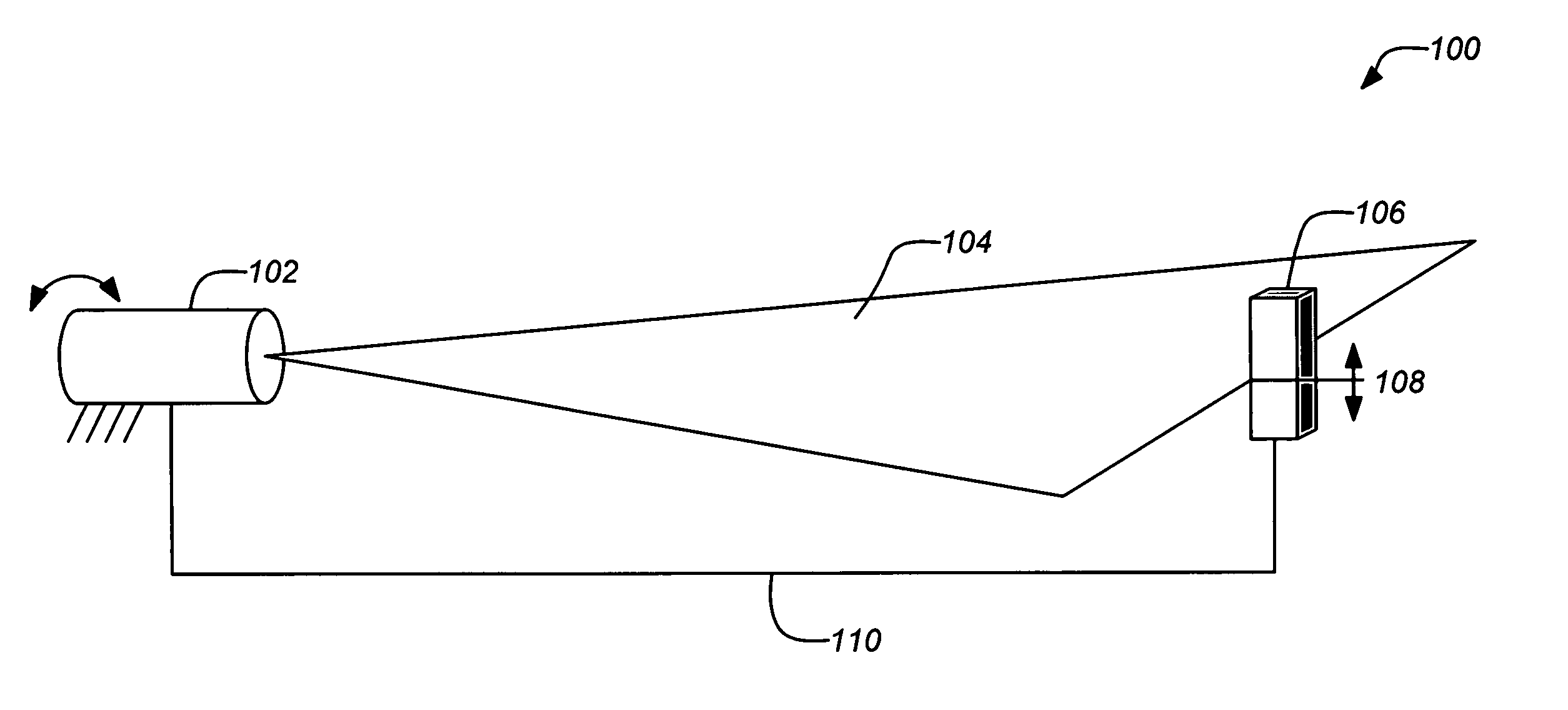
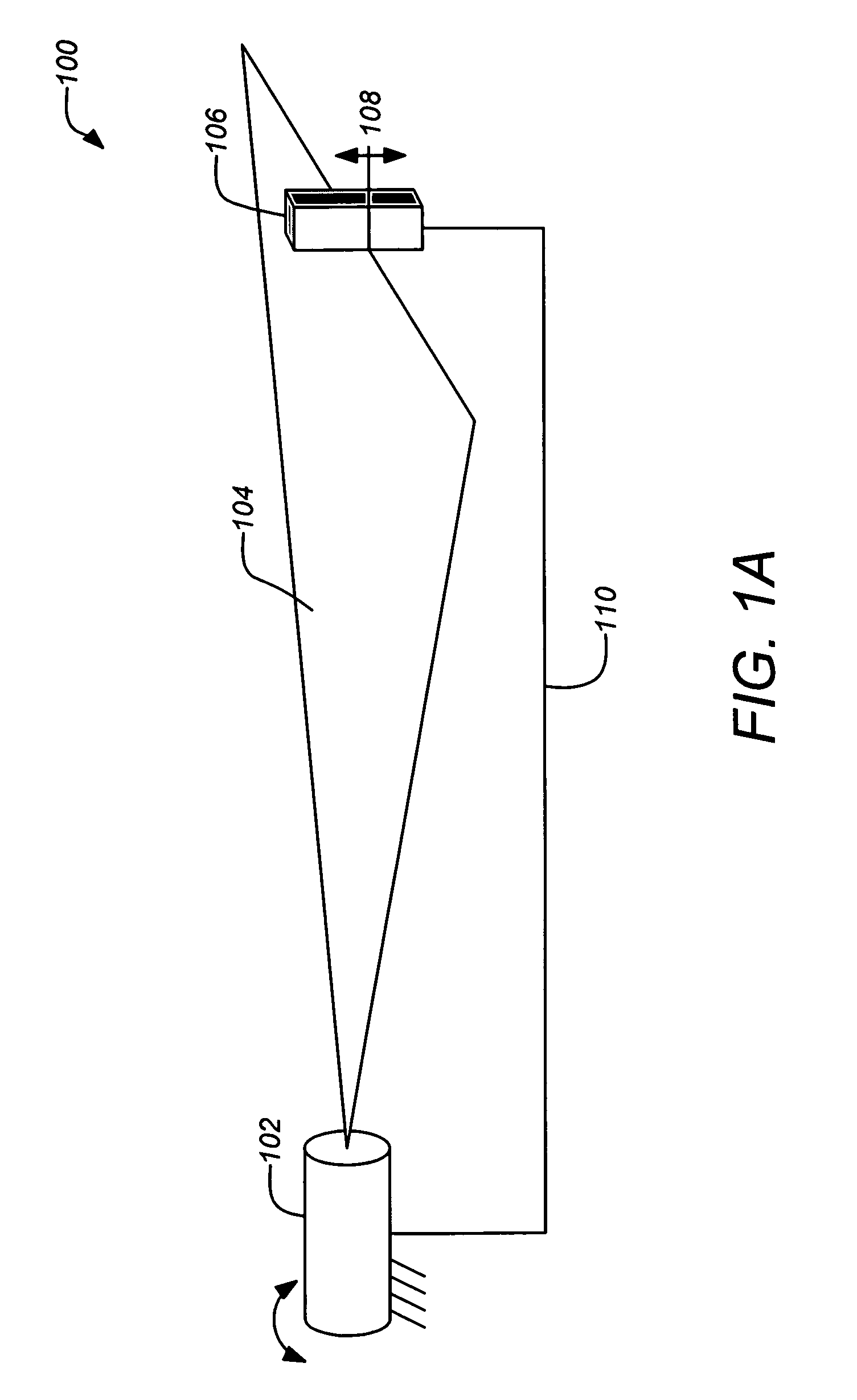
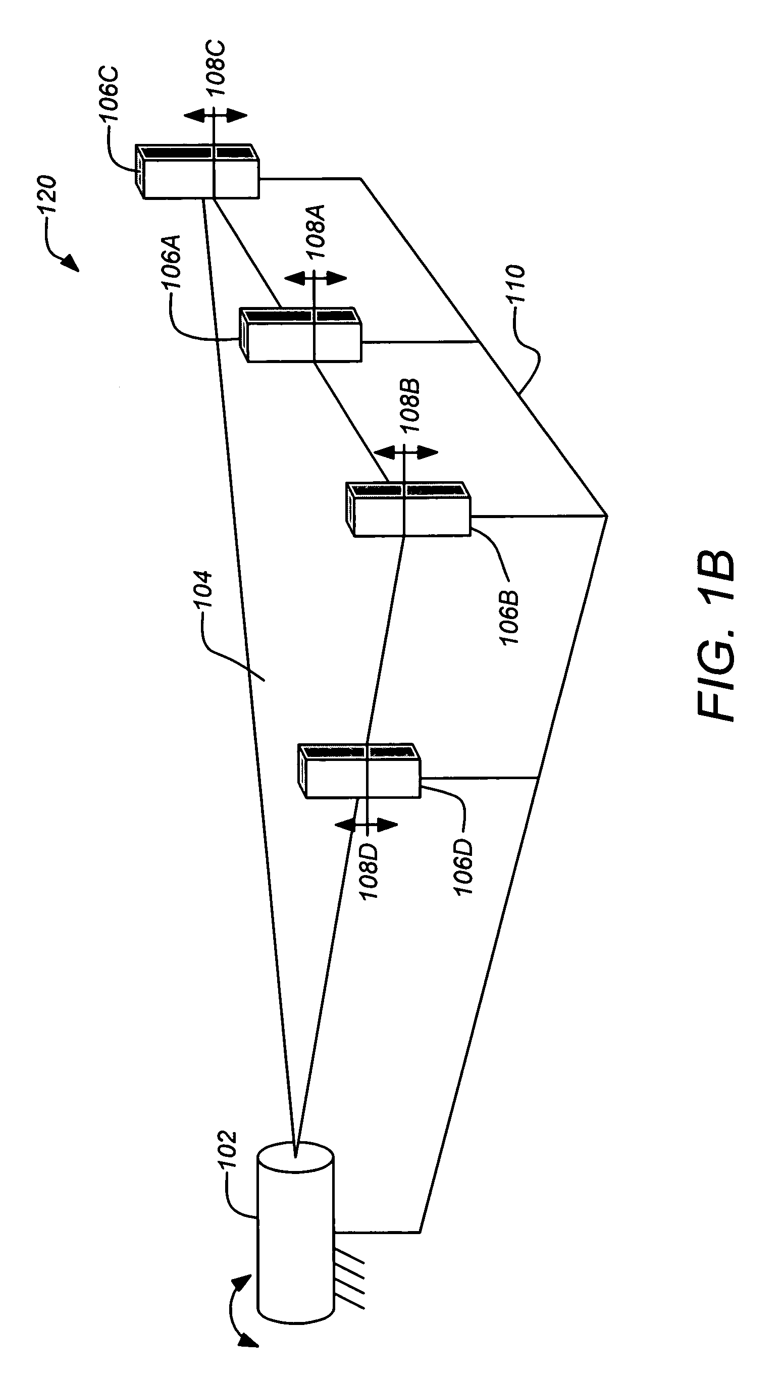
[0032]FIG. 1A is a schematic illustration of a foundational measurement unit 100 for a typical embodiment of the invention. It includes a laser beam transmitter 102 which transmits a fanned laser beam 104 at a fixed orientation (relative to a structure...


PUM


Abstract

One or more fixed-orientation fanned laser beams and one or more displacement measurement devices to precisely measure the orientation of a payload platform are disclosed in a metrology system and method. The measurement devices may be distributed at locations across a payload platform such that displacement changes of these devices can be used to accurately determine platform pointing. Laser beam transmitters may be fixed in the same reference block to which a spacecraft attitude sensor is mounted. Fanned laser beams are transmitted from these sources to the measurement devices so that their displacements can be determined with respect to the plane of the fanned beams and thereby with respect to the spacecraft attitude sensor. Only a small number of fixed laser beams are needed to achieve precision measurements at a reduced cost, weight and power, and with increased system reliability and simplified system integration.

Description

CROSS-REFERENCE TO RELATED APPLICATIONS [0001] This application claims the benefit under 35 U.S.C. §119(e) of the following co-pending U.S. Provisional Patent Application, which is incorporated by reference herein: [0002] U.S. Provisional Application Ser. No. 60 / 780,891, filed Mar. 9, 2006, by Liu et al., entitled “PRECISION SPACECRAFT PAYLOAD PLATFORMS”. [0003] This application is related to the following co-pending and commonly-assigned U.S. utility patent applications, which are both incorporated by reference herein: [0004] U.S. patent application Ser. No. 10 / 917,924, filed Aug. 12, 2004, by Liu et al., entitled “SMART SPACECRAFT STRUCTURES BASED ON LASER METROLOGY”; and [0005] U.S. patent application Ser. No. 11 / 270,000, filed Nov. 9, 2005, by Liu et al., entitled “FANNED LASER BEAM METROLOGY SYSTEM”.BACKGROUND OF THE INVENTION [0006] 1. Field of the Invention [0007] This invention relates to platform pointing as used in space applications. Particularly, this invention relates t...

Claims


Application Information

Patent Timeline
IPC IPC(8): G01N21/86
CPCG01S5/163G01B11/272
Inventor LIU, KETAOBECKER, GREGORY S.SEDIVEC, PETER J.BENDER, DOUGLAS
Owner THE BOEING CO
Why Eureka
Try Eureka