System for injecting reactants in an exhaust line

Inactive Publication Date: 2016-03-03
VOLVO LASTVAGNAR AB
View PDF1 Cites 11 Cited by
  • Summary
  • Abstract
  • Description
  • Claims
  • Application Information

AI Technical Summary

Benefits of technology

[0021]Another advantage of the invention lies in the fact that the injector can be simplified since it is less demanding on the quality of the injection spray at some difficult functioning points. Indeed, since injection of liquid reactant can be avoided under non-optimal operating conditions, there is less of a need to have a perfectly nebulized spray. Moreover, in some embodiments of the invention, injecting simultaneously both the liquid precursor and gaseous ammonia at the same time can be sufficient to get a satisfactory quality of injection spray at said functioning points, especially at operation points where conditions are borderline with respect to the liquid reactant.
[0022]Furthermore, owing to the provision of a single injector body, the invention improves compactness and simplifies the system integration in a small allocated space. This further allows reducing the system overall cost, also because there can be provided a single protection package of the various components of the injector assembly, especially a single heat protection package. Said protection package can be fairly complicated and expensive due to the constraints resulting from the hot environment.
[0023]In practice, there may be provided one or several first inlets, as well as one or several second inlets. The first inlet(s) and second inlet(s) can be separate. Alternatively, there may be provided one or several common inlets for the liquid precursor and for gaseous ammonia.
[0024]According to an embodiment, the injector body can comprise one or several common outlets for the liquid precursor and the gaseous ammonia. In such a case, the flow path of the liquid precursor and the flow pa

Problems solved by technology

One problem with this type of exhaust gases treatment system is that, in some operating conditions of the engine, especially when the temperature of the exhaust gases is relatively low, for example around 20.0° C., urea, and/or it's the intermediate product in its transformation into ammonia, can crystallize before it has transformed into ammonia.
One consequence is that the cross section of the exhaust pipe may be progressively reduced, which may decrease the engine efficiency and which can seriously impair the engine operati

Method used


Image

  • System for injecting reactants in an exhaust line
  • System for injecting reactants in an exhaust line
  • System for injecting reactants in an exhaust line

Examples


first embodiment

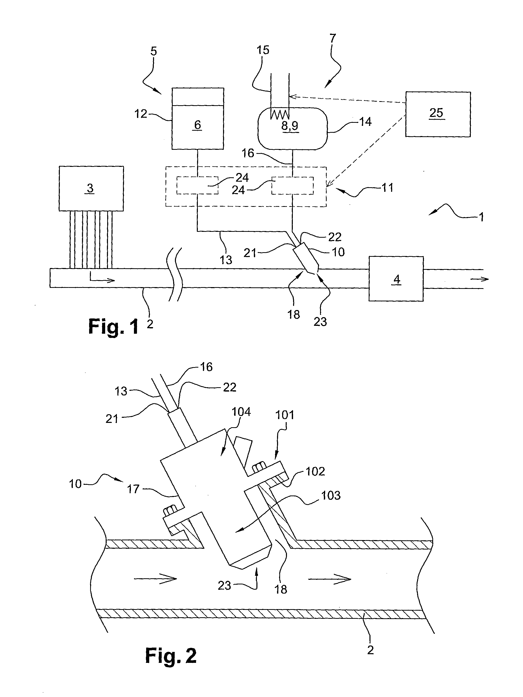
[0042]FIG. 1 schematically shows a system 1 for injecting reactant(s) in an exhaust line of an engine, especially in view of treating nitrogen oxides (NOx) contained in the exhaust gases produced by an automotive vehicle engine, especially by an internal combustion engine 3. The engine 3 may be a Diesel engine.

[0043]An exhaust line 2 carries exhaust gases from an engine 3 towards the atmosphere. In the exhaust line 2 is provided a selective catalytic reduction (SCR) device 4 in which NOx can be converted essentially into water and nitrogen by means of ammonia used as a reductant.

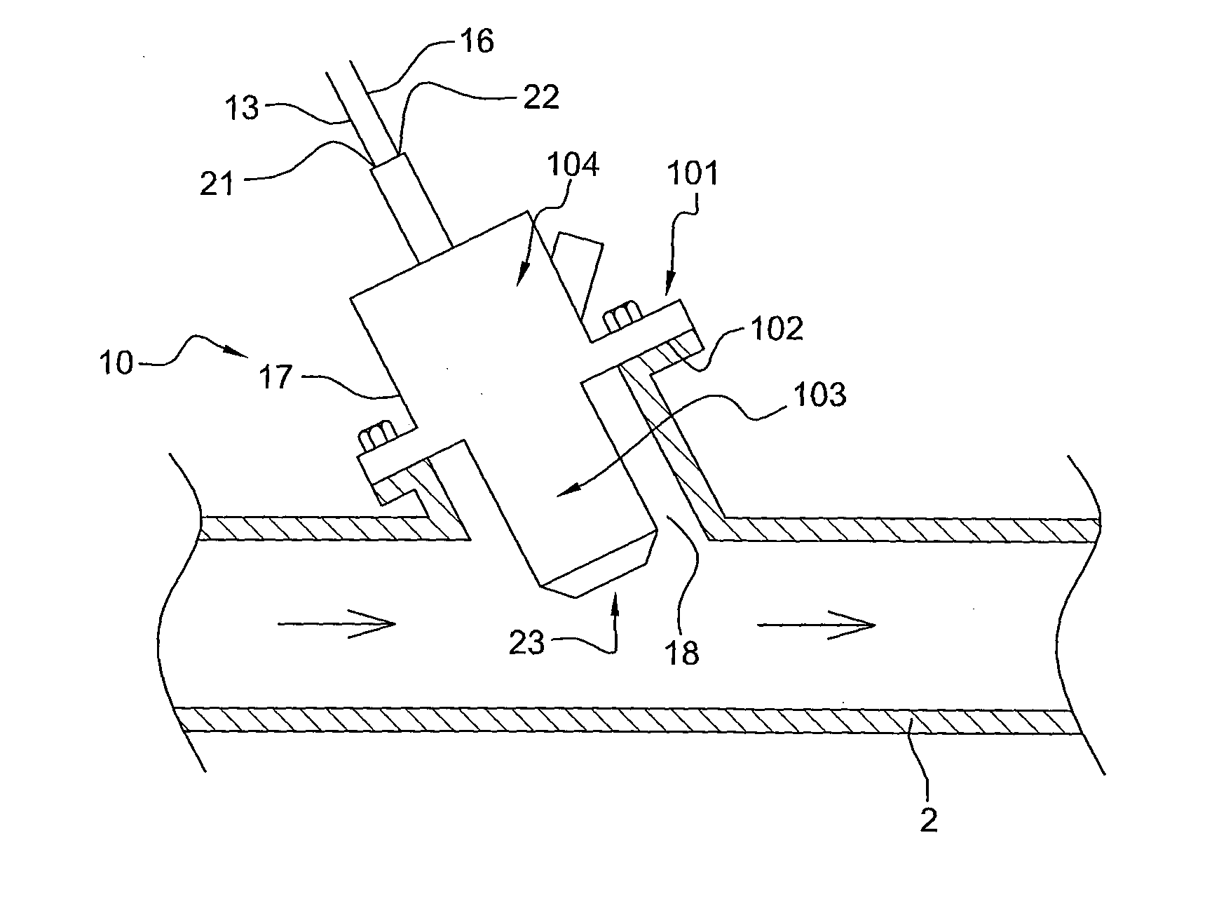
[0044]The system 1 basically comprises a double source of ammonia, namely a source 5 of a liquid precursor 6 of ammonia and a source 7 of gaseous ammonia 8, an injection assembly comprising an injector 10 fitted on the exhaust line 2 to inject liquid precursor and / or gaseous ammonia inside the exhaust line 2.

[0045]The injector 10 is preferably located on the exhaust line 2 upstream from the SCR device 4.

[004...

second embodiment

[0093] depicted in FIG. 8, the liquid circuit 13 and the gas circuit 16 merge upstream from the injector 10, which therefore may have a common inlet for both the gaseous ammonia and the liquid precursor. A common dosing device 24c can be arranged at the connecting point between these circuits 13, 16 to let the appropriate reductant, or the appropriate mixture of both reductants, flow towards the injector 10. The dosing device 24c can comprise a three position valve, but this implementation is not limitative. Additional components of the flow control system 11 can also be provided on the corresponding circuits 13, 16. In this embodiment, the injector 10 is preferably a controlled injector 10.

[0094]This embodiment is advantageous in that it can be fairly inexpensive insofar as a single dosing device 24c may be provided.

third embodiment

[0095] depicted in FIG. 9, the system 1 can further comprise an air line 35 for carrying pressurized air 36 towards an inlet of the injector body 17, in order to assist the injection of the liquid precursor 6. The injector body could include a dedicated air inlet.

[0096]In practice, the air line 35 can be fluidically connected to the gas circuit 16, upstream from the injector 0. A valve 37 may be arranged at the connecting point of the air line 35 and the gas circuit 16 to direct either gaseous ammonia 8 or air 36 towards the injector 10. Air 36 can come from an air source of the vehicle or can be generated by an external source, such as a mechanical or electrical air pump.

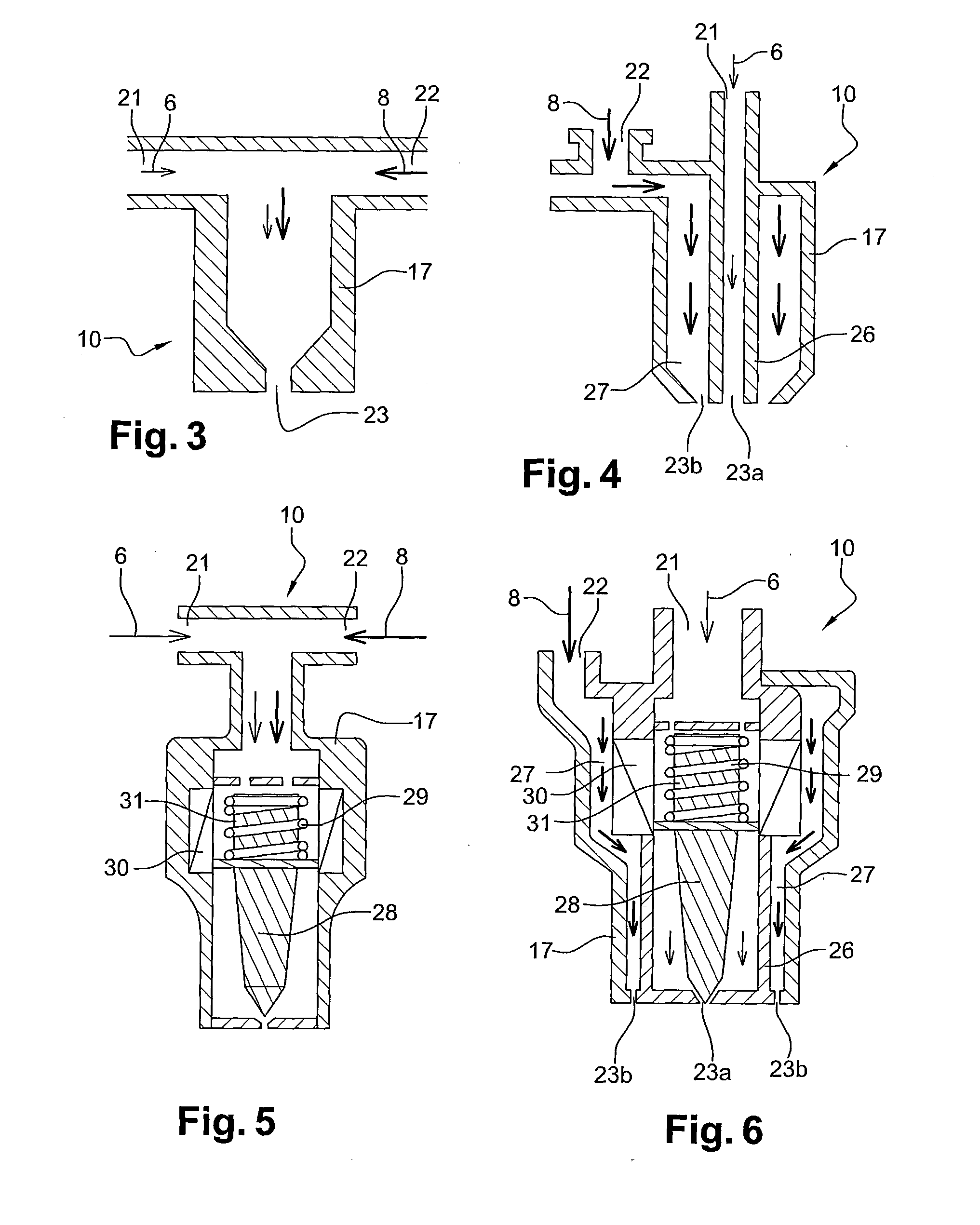
[0097]The embodiment of FIG. 9, with an additional air line 35 is preferably implemented with an injector comprising fully separate flow paths for the liquid precursor and for the gaseous ammonia inside the injector body, such as one of the injectors shown on FIG. 4 or 6 or any of their variants.

[0098]Depending on ...


PUM


Abstract

A system to be fitted on an automotive vehicle for injecting reactants in an exhaust line of an engine of the vehicle includes a source of a liquid precursor of ammonia, a source of gaseous ammonia, an injection assembly designed to be fitted on the exhaust line and to inject liquid precursor and/or gaseous ammonia inside the exhaust line, the injection assembly including a single injector body to be fitted on the exhaust line, the injector body having a first inlet for the liquid precursor, a second inlet for the gaseous ammonia, and at least one outlet for injection inside the exhaust line.

Description

BACKGROUND AND SUMMARY[0001]The present invention relates to a system for injecting reactant(s) in an exhaust line of an engine. It may be used in the context of treating nitrogen oxides contained in exhaust gases flowing in an exhaust line of the engine, especially but not exclusively in a vehicle.[0002]Exhaust gases formed due to the combustion of fuel in an internal combustion engine may contain a proportion of undesirable components, in particular nitrogen oxides (NOx).[0003]Various exhaust after-treatment systems are known for removing or reducing the amount of undesirable components. Some of these systems require that at least one reactant fluid is injected in the exhaust line to react with the exhaust gases, either directly, or indirectly after having undergone one or several chemical transportation, and / or with the help of catalysts.[0004]One known example of such an exhaust after-treatment system is the so-called selective catalytic reduction (SCR) system which has been imp...

Claims


Application Information

Patent Timeline
IPC IPC(8): F01N3/28F01N3/20
CPCF01N2610/06F01N3/2896F01N2610/02F01N2610/01F01N3/2066F01N3/208F01N2610/10F01N2610/107F01N2610/12F01N2610/146Y02T10/24F01N2610/08Y02A50/20Y02T10/12
Inventor PRAMAS, MARTINHEDNA, MOURAD
Owner VOLVO LASTVAGNAR AB
Why Eureka
Try Eureka