Multi-ply platforms and panels using such a platform

a technology of multi-ply platforms and panels, applied in the field of multi-ply platforms, can solve the problems of deformation of decorative surfaces, unbalanced products, swelling and contraction of fibres, etc., and achieve the effect of improving the resistance to deformation

Inactive Publication Date: 2010-12-30
NORLING HAKAN +1
View PDF8 Cites 36 Cited by
  • Summary
  • Abstract
  • Description
  • Claims
  • Application Information

AI Technical Summary

Benefits of technology

[0007]An object of the present invention is to provide multi-ply platforms suitable for the manufacture of decorative panels, and decorative panels incorporating such multi-ply platforms, which multi-ply platforms improve the resistance to deformation caused by changes in relative humidity and / or temperature of, or around, such decorative panels.

Problems solved by technology

This leads to an unbalanced product as the formerly balanced plywood platform has the decorative veneer only attached to one face.
When such decorative panels are subjected to changes in relative humidity, e.g. from 10% relative humidity during the winter months to 80-90% relative humidity during the summer, or large changes of temperature, deformations in the decorative surface may occur as the swelling and contraction of the fibres of the decorative veneer cannot be balanced by the underlying plywood platform.

Method used


Image

  • Multi-ply platforms and panels using such a platform
  • Multi-ply platforms and panels using such a platform
  • Multi-ply platforms and panels using such a platform

Examples


first embodiment

[0032]FIG. 3a) shows schematically in perspective an exploded view of the plies of a 4-ply multi-ply platform 21 in accordance with the present invention. Platform 21 is intended to be joined with a decorative lamella which has its grain direction in the longitudinal direction in order to form a decorated panel, e.g. for use as a wall or floor. Platform 21 comprises 4 veneers 23, 25, 27, 29 arranged in a pile with their edges aligned. Contrary to the construction normally used in prior art plywood sheets, the veneers are not arranged with alternating grain directions. Veneer 23 is a face ply and has a visible working surface 31 which is intended to receive a decorative lamella when the platform is made into a decorated panel. Veneer 23 has a grain direction which is substantially perpendicular to the grain direction of the decorative lamella which is intended to be attached to it. Veneer 25 is also a face ply and it has a grain direction which is parallel with the grain direction of...

second embodiment

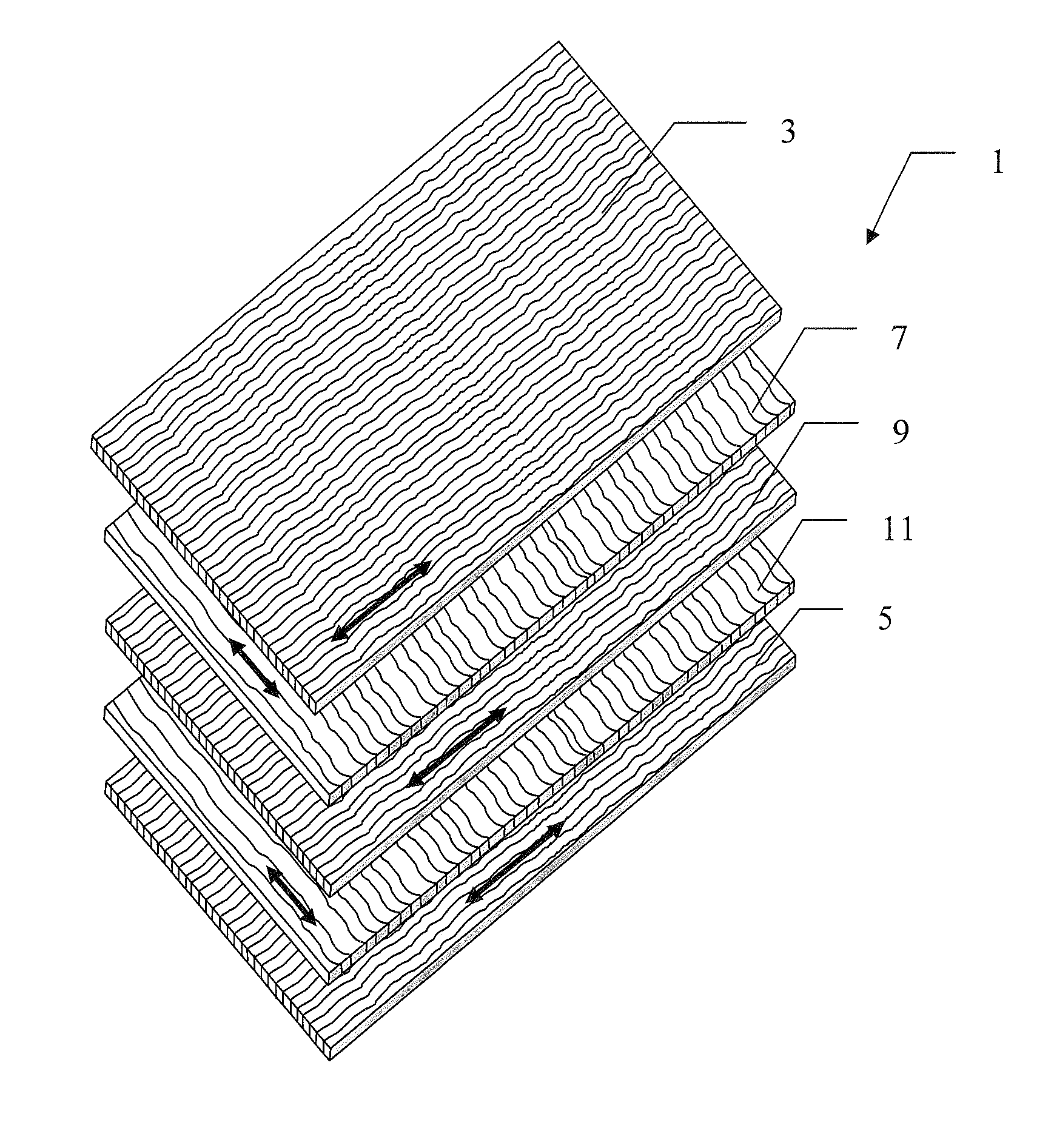
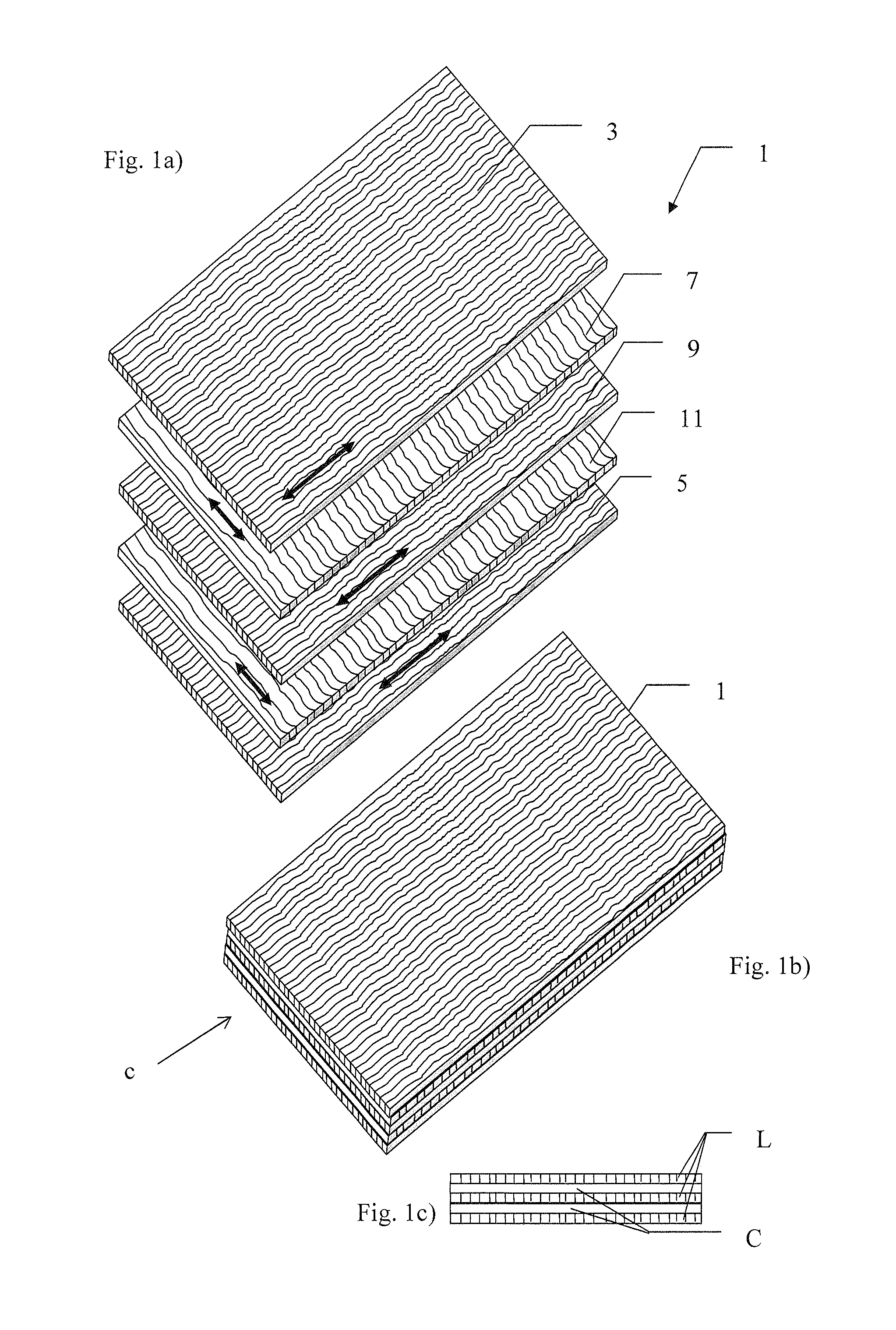
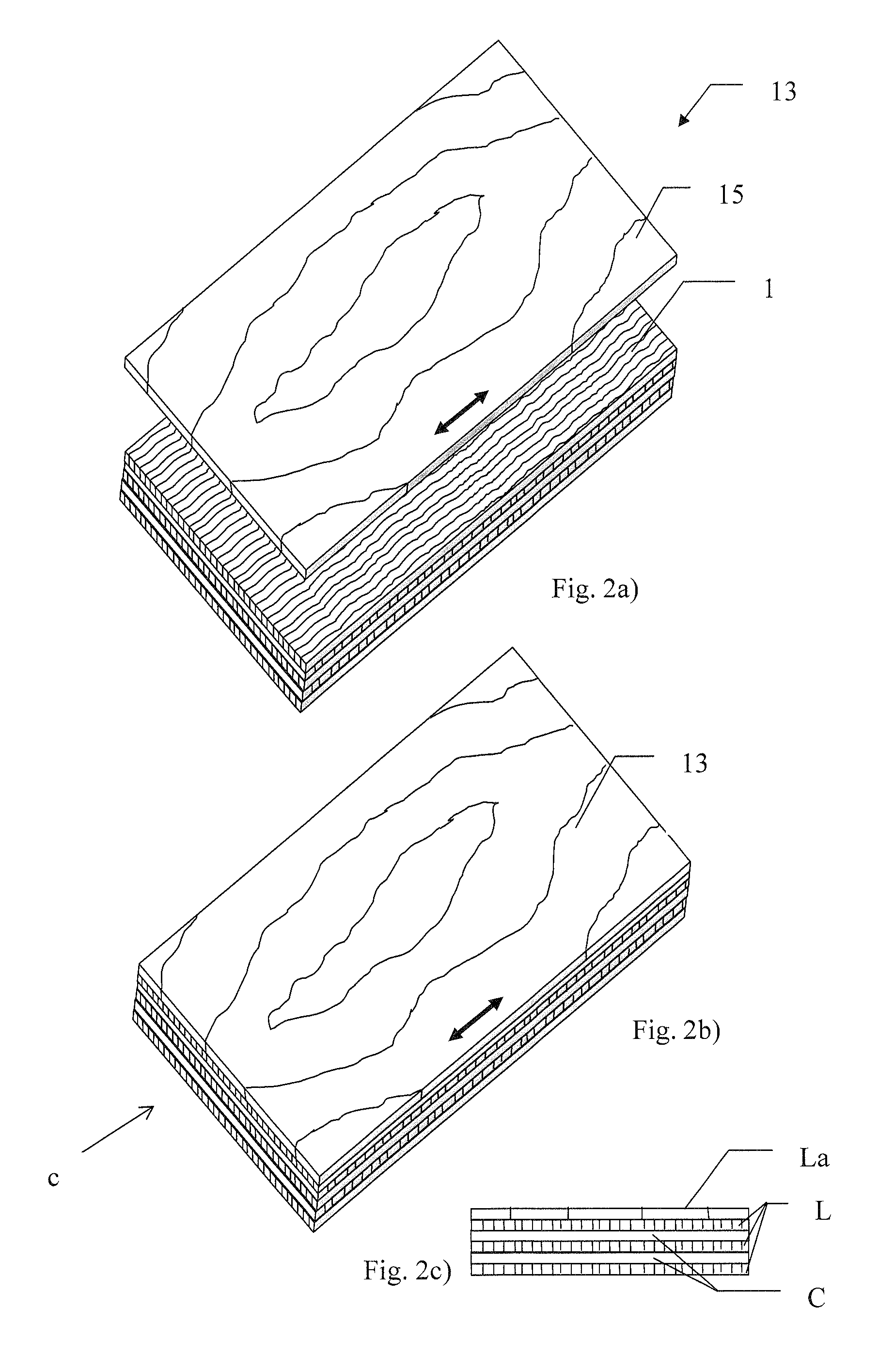
[0037]In the present invention, an unbalanced multi-ply platform comprises three plies. In the event that the multi-ply platform is intended to be used with a lamella in which the grain direction of the material of the lamella is in the longitudinal direction then the multi-ply platform would have a ply structure C-C-L, the lamella being attached to the outermost C ply to form a multi-ply panel with plies arranged Lamella-C-C-L. Conversely, in the event that the multi-ply platform is intended to be used with a lamella in which the grain direction of the material of the lamella has is in the cross direction then the multi-ply platform would have a ply structure L-L-C, the lamella being attached to the outermost L ply to form a multi-ply panel with plies arranged La-L-L-C.

[0038]Other embodiments of unbalanced platforms in accordance with the present invention are also conceivable where more that 3 consecutive plies have substantially the same grain direction, for example C-C-C-C . . ....


PUM


Abstract

A multi-ply platform suitable for the manufacture of decorative panels and decorative panels incorporating such multi-ply platforms, which has improved resistance to deformation caused by changes in relative humidity and/or temperature of, or around, such decorative panels. This multi-ply platform includes a plurality of plies which are arranged so that the platform is substantially unbalanced around its central plane. The unbalanced platform is achieved by, arranging the plies such that at least two adjacent plies have substantially the same main grain direction and/or that two plies having substantially the same main grain direction are separated only by one or more neutral plies. These unbalanced platforms are intended to be bonded to a further ply to form a substantially balanced decorative panel.

Description

FIELD OF THE INVENTION[0001]The present invention relates to multi-ply platforms for the manufacture of floor and wall panels and floor and wall panels made using such multi-ply platforms.BACKGROUND ART[0002]Plywood is an example of a multi-ply product—that is a product which is made of a plurality of layers of sheet material in which the faces of adjacent sheets are bonded to each other. Plywood is a panel product manufactured by gluing together one or more veneers to both sides of a veneer, solid wood, or reconstituted wood core. In the case of solid-wood-core plywood and reconstituted-wood-core plywood, an additional intermediate step is the production of cores, which are made by lateral gluing of blocks or strips of wood or by gluing oriented wood chips with resin adhesives. Plywood has many advantages over natural wood, an important one being greater dimensional stability. Its uniformity of strength, resistance to splitting, panel form, and decorative value make it adaptable to...

Claims


Application Information

Patent Timeline
Patent Type & Authority Applications(United States)
IPC IPC(8): E04C2/38B32B7/03
CPCB32B21/14B32B21/042B32B2471/00Y10T428/195B27D1/04B32B21/13B32B7/005B32B21/04B32B7/12B32B2307/734Y10T428/24058Y10T428/24066Y10T428/24777E04C2/24B32B21/02Y10T428/24132B32B2607/00B32B3/06E04C2/12E04F15/046B32B7/03Y10T428/31989
Inventor NORLING, HAKANKEMMSIES, MARTIN
Owner NORLING HAKAN
Why Eureka
Try Eureka