Modular freezer rack

a freezer rack and module technology, applied in the field of modules, can solve the problems of inconvenient storage, inconvenient storage, and bulky items in conventional freezer racks, and achieve the effect of reducing costs

Inactive Publication Date: 2010-12-30
LABNET INT
View PDF17 Cites 9 Cited by
  • Summary
  • Abstract
  • Description
  • Claims
  • Application Information

AI Technical Summary

Benefits of technology

[0004]A rack for providing a lower cost solution for manufacturing and shipping is disclosed. The rack, suitable for use in freezer or cooling components comprises a top element, a bottom element and side elements between said top and bottom elements, linearly arranged, wherein four of said elements are joined together at three shared edges with a flexible hinge mechanism, a joining mechanism including a catching mechanism and a connecting mechanism, said joining mechanism retaining adjacent ones of

Problems solved by technology

The boxes and the tube holder frame can be made from cardboard (inexpensive, but not very durable), or plastic (such as polypropylene, or polycarbonate, typically with drain holes for liquid nitrogen storage).
However, conventional freezer racks a

Method used


Image

  • Modular freezer rack
  • Modular freezer rack
  • Modular freezer rack

Examples


Embodiment Construction

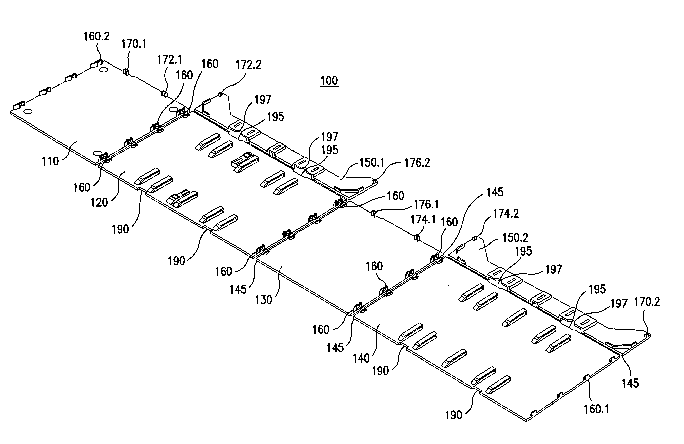
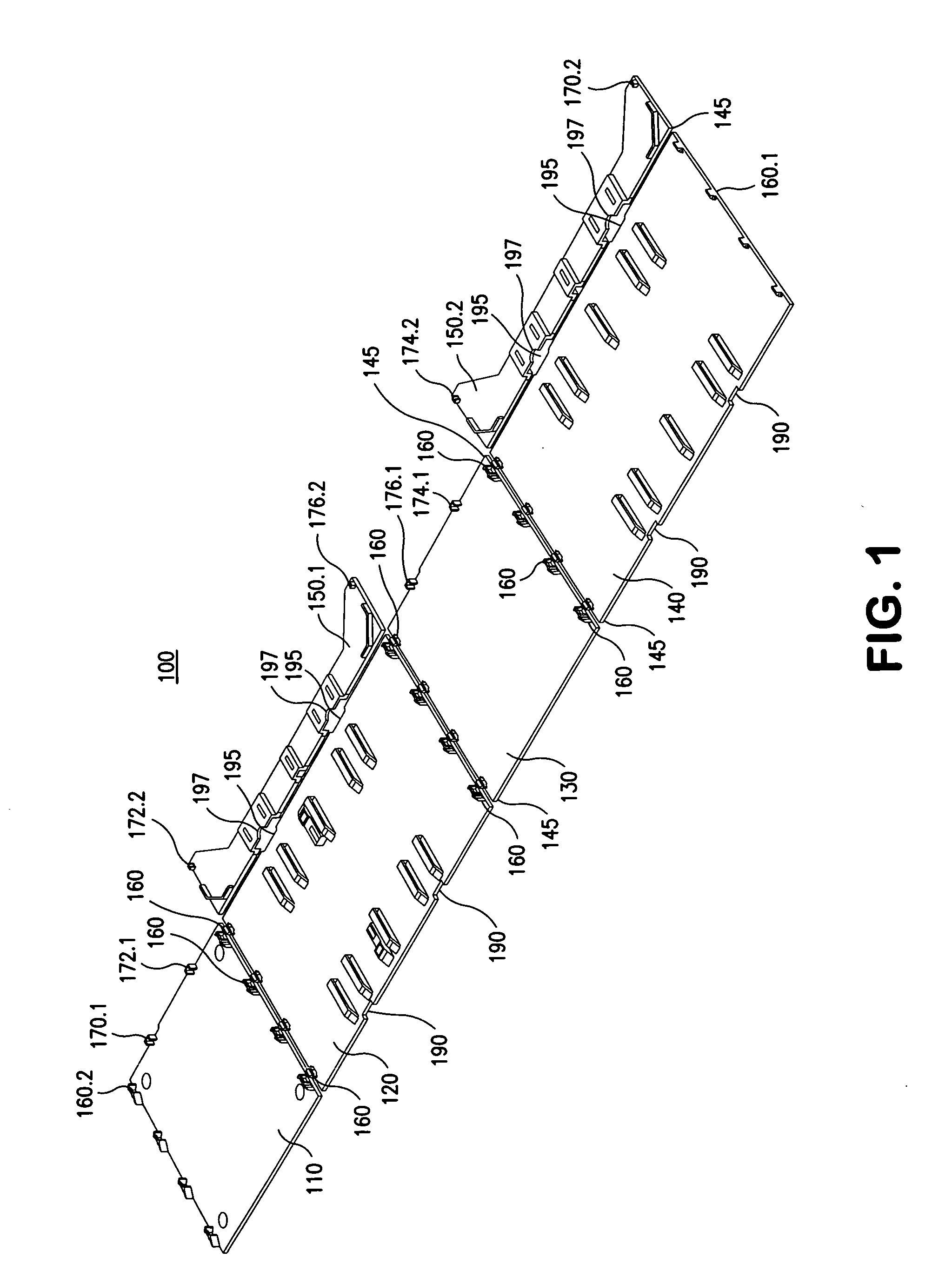
[0016]FIG. 1 illustrates an exemplary freezer rack 100 in accordance with a first, unfolded, state, including top member 110, first side member 120, bottom member 130 and second side member 140, which are linearly joined together. First side member 120 and second side member 140 each includes a back surface 150.1, 150.2 linearly joined at back edge of the first and second side members. Back surface 150.1, 150.2, preferably, are limited is size to create a back surface that is not fully closed. However, it would be appreciated that back surface 150.1, 150.2 may be sized to provide a fully closed back surface when the freezer rack 100 is in a second, folded, state. In the embodiment shown in FIG. 1, the bottom element 130 is positioned between and adjacent to the side elements 120, 140. However, it would be recognized that it may be possible to provide an embodiment of the invention wherein a top member 110 may be positioned between and adjacent to side members 140 and 120 or a side m...


PUM


Abstract

A rack for providing a lower cost solution for manufacturing and shipping is disclosed. The rack, suitable for use in freezer or cooling components comprises a top element, a bottom element and side elements between said top and bottom elements, linearly arranged, wherein three of said elements are joined together at corresponding edges with a flexible hinge mechanism, a joining mechanism including a catching mechanism and a connecting mechanism, said joining mechanism retaining adjacent ones of said elements in a substantially perpendicular arrangement, each of said elements including at least one of said catching mechanism and said connecting mechanism and adjacent ones of said elements contain alternate ones of said catching mechanism and said connecting mechanism; and a back element linearly attached with a flexible hinge mechanism along an edge of each of said side elements, wherein said back element includes a snap fit retaining mechanism along a top end and a bottom end of each edge.

Description

BACKGROUND OF THE INVENTION[0001]Storage of biological samples often requires the use of a refrigerator and / or freezer unit. Such samples are commonly sealed in plastic micro-tubes (such as Cryovial brand from Simport Plastiques Ltee, Beloeil, Quebec, Canada), which are small vessels, each of which typically holds a total volume of 1 to 3 milliliters, and has a separate sealing screw cap. These tubes are commonly organized in standard 81-place (9×9 configuration) or 100-place (10×10 configuration) storage boxes or trays. The boxes and the tube holder frame can be made from cardboard (inexpensive, but not very durable), or plastic (such as polypropylene, or polycarbonate, typically with drain holes for liquid nitrogen storage). These boxes are available in different heights (typically 2 inches high or 3 inches high) to accommodate the most popular sized sample tubes. Another popular method stores samples in 96-well or 384-well microtiter plates with sealing lids, or small tubes that ...

Claims


Application Information

Patent Timeline
IPC IPC(8): A47B47/00A47B96/02A47B96/00
CPCA47B43/00B01L7/50B01L9/06F25D25/02B01L2300/0829F16B12/26B01L9/523
Inventor ROSENBLUM, MICHAEL D.
Owner LABNET INT
Why Eureka
Try Eureka