Method of and apparatus for bouyancy compensation for divers

a technology of bouyancy compensation and equipment, which is applied in the direction of underwater equipment, waterborne vessels, transportation and packaging, etc., can solve the problems of difficult for a diver to stay submerged, difficult for a diver to overcome the tendency to sink, and not only a nuisance, but also a bit of danger

Active Publication Date: 2010-12-30
MARKS LLOYD A
View PDF22 Cites 6 Cited by
  • Summary
  • Abstract
  • Description
  • Claims
  • Application Information

AI Technical Summary

Benefits of technology

[0032]When a plurality of elastic members, e.g., four, is used in the BCD of the invention, flow restrictors may be included in the inlet to each elastic member should the elastic members not inflate uniform...

Problems solved by technology

Thus, the diver may have to overcome the tendency to sink.
Thus, at the end of a dive, it may be difficult for a diver to stay submerged for a safety stop (to prevent decompression illness).
Apart from having to carry the extra weight, this presents another problem for the diver.
However, the latter situation is not only a nuisance, but can be quite dangerous.
If a diver ascends to the surface using a conventional BCD without carefully controlling his rate of ascent by releasing air from the BCD, the air in the BCD will increase in volume making him ascend faster, which further increases the BCD volume and so on, resulting in an “uncontrolled ascent.” An uncontrolled ascent can cause two serious problems.
One of these problems is decompression sickness, commonly called “the bends,” which is caused by the release of dissolved nitrogen as a gas into the blood stream.
An equally, if not more, serious problem can be caused by a rapid increase in the total lung volume.
This, in turn, will cause an increase in lung volume beyond that which the lungs are capable of accommodating, which may rupture the alveoli, resulting in a pneumothorax.
A pneumothorax can be fatal and is a common cause of death for the novice or panicked diver.
As the air in the conventional BCD bladder expands upon ascending, the diver will tend to ascend faster which, in turn, increases lift more rapidly and causes acceleration of the diver's rate of ascension, an extremely dangerous condition, especially if a decompression stop is necessary before surfacing.
Occasionally, even experienced divers do not accurately adjust the release of air from the conventional BCD and accidentally bypass a decompression stop.
Another problem can occur when a diver, experienced or not, wears a thick and, therefore, very buoyant wetsuit.
Then, when the wetsuit compresses, the diver becomes negatively buoyant to a degree that requires a sign...

Method used


Image

  • Method of and apparatus for bouyancy compensation for divers
  • Method of and apparatus for bouyancy compensation for divers
  • Method of and apparatus for bouyancy compensation for divers

Examples


Embodiment Construction

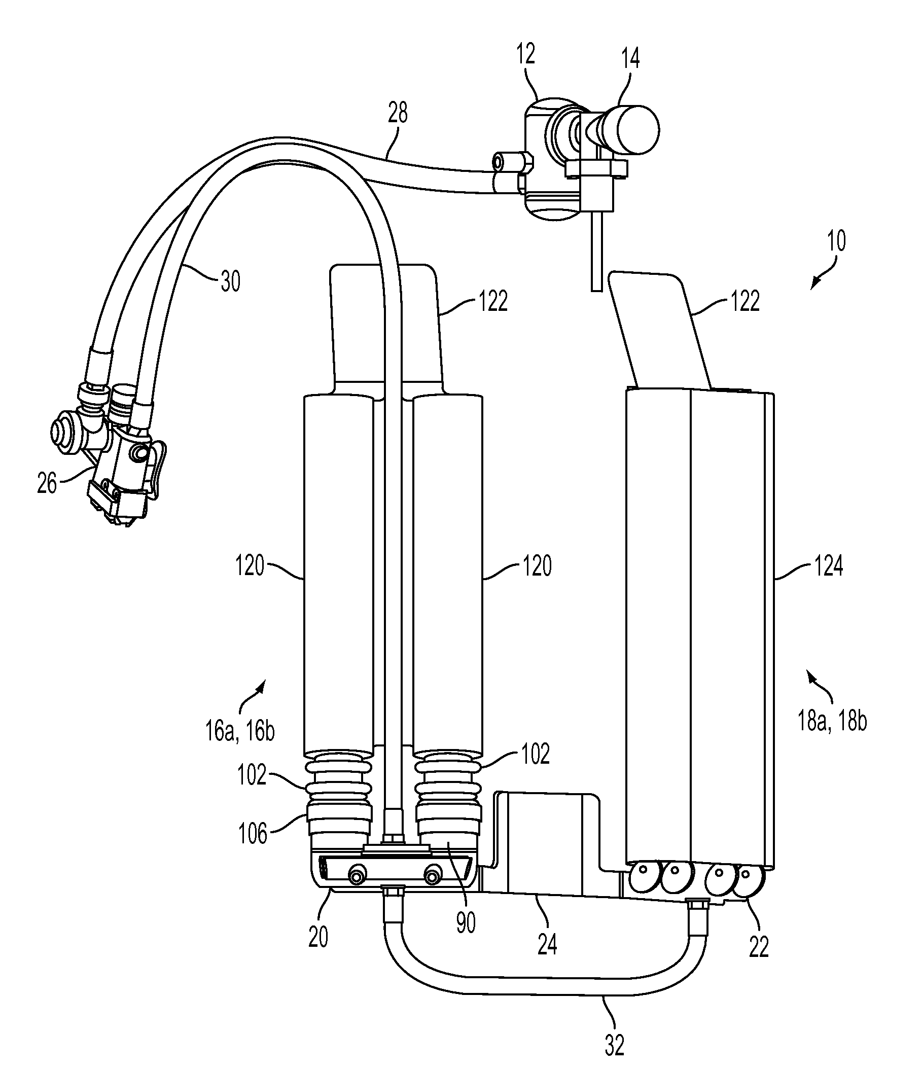
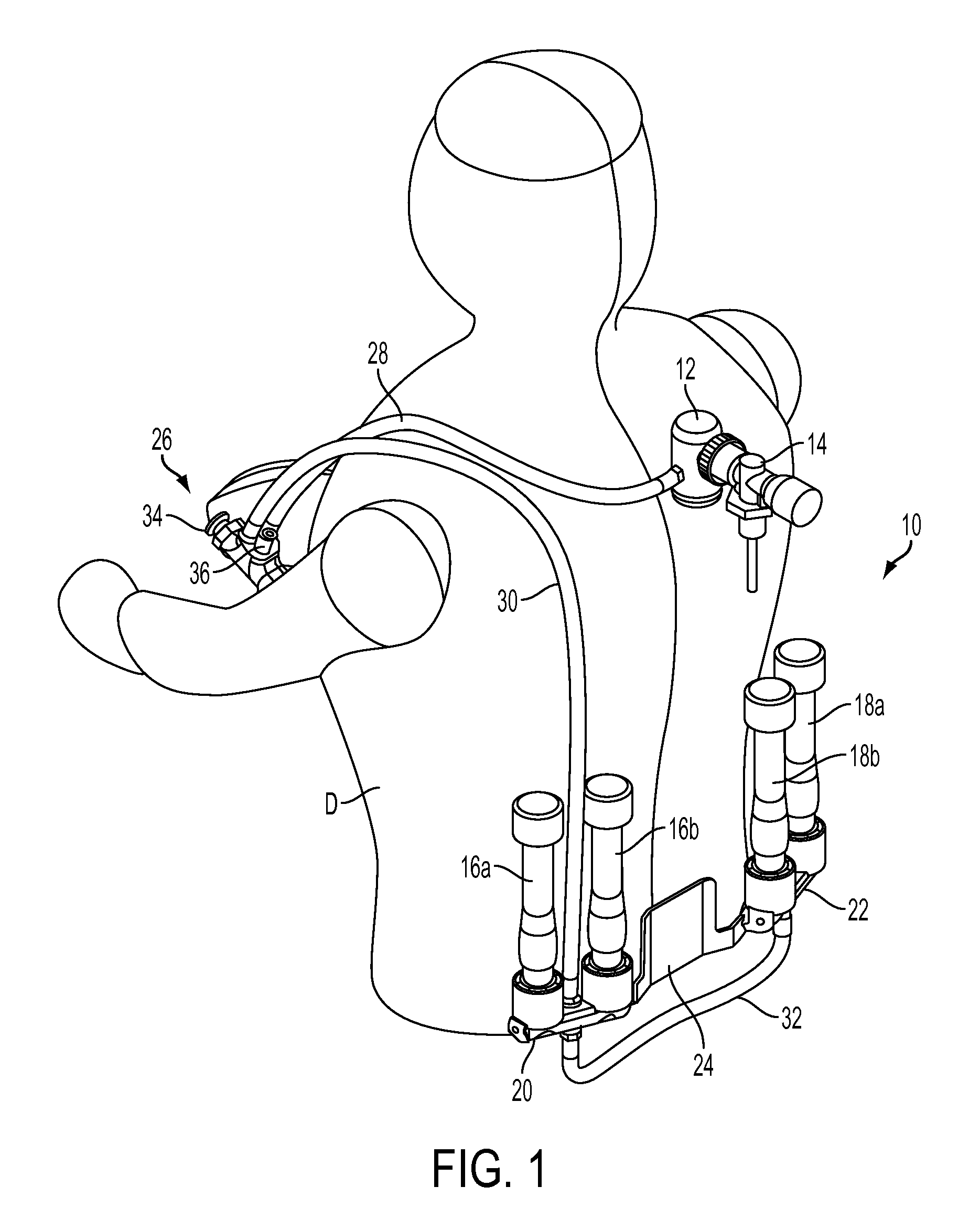
[0045]Referring now to FIG. 1 of the drawings, an embodiment of the BCD of the invention is illustrated in perspective on the body of a diver D and is designated generally with reference numeral 10. In the FIG. 1 illustration, the diver's conventional SCUBA equipment is not shown, apart from the first stage regulator 12 and the valve 14 which is connected between the first stage regulator and the pressurized tank of the SCUBA equipment. The BCD 10 of the invention comprises four elastic tubular members 16a, 16b, 18a and 18b, which are vertically arranged in two pair 16a, 16b and 18a, 18b, respectively, on opposite sides of the diver's lower back. The structure of the elastic tubular members is described in more detail hereinafter in connection with FIGS. 3A, 3B, 4A and 4B. Each pair of tubular members is connected to a respective left and right manifold 20, 22, which, in turn, are affixed to a manifold mounting bracket 24. Bracket 24 is mounted on the diver's SCUBA equipment (not sh...


PUM


Abstract

An improved buoyancy compensation device having a lesser change in buoyancy with depth than conventional buoyancy compensation devices which use ambient pressure bladders is disclosed. The improved device comprises one or more elastic members that, throughout the working range of diving pressures and volumes, is always elastic and, when pressurized, maintains an internal air pressure that is always greater than the ambient pressure at any dive depth. The invention also relates to a method of providing a buoyancy compensation device with an elastic member having a lift versus depth characteristic that approaches the lift versus depth characteristic of a constant or fixed volume buoyancy compensation device.

Description

BACKGROUND OF THE INVENTION[0001]1. Field of the Invention[0002]The present invention relates to buoyancy compensation devices for use by underwater divers, especially recreational SCUBA divers, and more particularly to a buoyancy compensation device that provides relatively constant buoyancy regardless of the diver's depth and a method of providing buoyancy compensation at relatively constant buoyancy for an underwater diver regardless of the diver's depth.[0003]2. Description of the Prior Art[0004]Typically, a SCUBA diver with dive gear, including a wetsuit and air tank, is positively buoyant and must wear lead weights in order to submerge. When the diver enters the water, the wetsuit has maximum buoyancy owing to the air in the pores of the expanded neoprene or butyl rubber from which wetsuits are typically made. As the wetsuit gets soaked with exposure to water and the air in the wetsuit is compressed as the diver descends to depths having pressures greater than atmospheric, it ...

Claims


Application Information

Patent Timeline
IPC IPC(8): B63C11/02B63C11/00
CPCB63C11/08B63C2011/085B63C11/2245
Inventor MARKS, LLOYD A.WEBER, DAVID W.
Owner MARKS LLOYD A
Why Eureka
Try Eureka