
Hydrodynamic coupling arrangement

a technology of coupling arrangement and hydraulic coupling, which is applied in the direction of fluid gearing, belt/chain/gearing, fluid gearing, etc., can solve the problems of unwanted axial displacement of the piston and difficult cleaning of the piston

Active Publication Date: 2022-02-22
ZF FRIEDRICHSHAFEN AG
View PDF12 Cites 0 Cited by
  • Summary
  • Abstract
  • Description
  • Claims
  • Application Information

AI Technical Summary

Benefits of technology

The invention relates to a device for controlling the pressure in a clutch system. The device includes a retarding device that slows down the rotational speed of the pressure medium on the input side of the piston to prevent an unwanted operational pressure difference on both sides of the piston. This prevents unbalanced operation during engagement or disengagement of the clutch. The retarding device has a swirl blading with at least one swirl blade that acts on the pressure medium in the pressure space. The swirl blade can be connected to the blade hub or the supply hub, and it can be formed with a blade carrier and a blade carrier segment that is separated from the blade carrier by clearance machining. The technical effect of the invention is to prevent operational pressure differences and improve the performance of the clutch system during engagement or disengagement.

Problems solved by technology

Assuming an open clutch device, a considerable difference in pressure would be observed because of the different rotational speeds of the pressure medium in the pressure space and in the toroidal space, which can lead to unwanted axial displacement of the piston.
Since this pressure difference varies depending on the respective speed, a clean engagement of the piston is problematic.

Method used


Image

  • Hydrodynamic coupling arrangement
  • Hydrodynamic coupling arrangement
  • Hydrodynamic coupling arrangement

Examples


Embodiment Construction

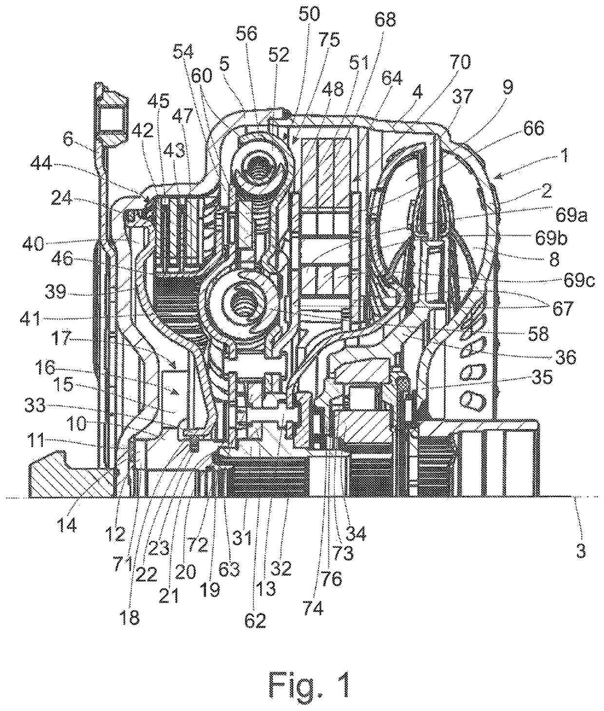
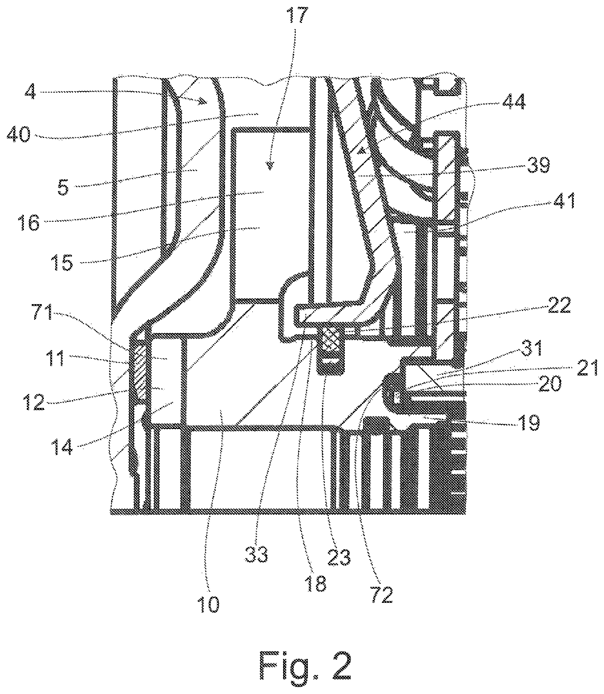
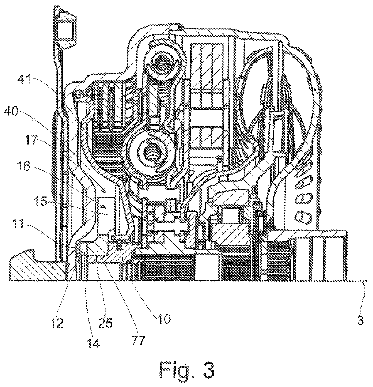
[0055]FIG. 1 is a sectional view showing a coupling arrangement 1 in the form of a hydrodynamic torque converter 2. A housing 4 which is rotatable around a central axis 3 is provided at its side facing a drive, such as an internal combustion engine, with a housing cover 5 to which a drive plate 6 is fastened. The drive plate 6 can be connected via a flexplate, not shown, to a crankshaft of the drive so as to be fixed with respect to rotation relative to it. A flexplate of this kind and the crankshaft of the drive connected to it are shown in DE 32 22 119 C1 in FIG. 1.

[0056]At its side remote of the housing cover 5, the housing 4 forms an impeller 8 with which a turbine 9 is associated axially opposite. The turbine 9 is connected via a plurality of fastening elements 13 provided along its circumference to an output hub 31 so as to be fixed with respect to rotation relative to it. The output hub 31 is connected to an output, not shown, such as a transmission input shaft of a transmiss...


PUM


Abstract

A hydrodynamic coupling arrangement has a housing connected to pressure medium lines for conducting pressure medium into or out of a pressure space sealed by a piston of a clutch device relative to a toroidal space of a hydrodynamic circuit provided in the housing. A rotatable area is provided for axially displaceably receiving a radially inner piston hub of the piston of the clutch device, and at least one through-opening which is rotatable relative to the housing is provided in a through-opening area for producing at least one flow connection between at least one pressure medium line and the pressure space. The receiving area and the through-opening area are in rotational communication with a retarding device influencing a flow of pressure medium in the pressure space, this flow of pressure medium arriving in the pressure space after passing through the through-opening area.

Description

CROSS REFERENCE TO RELATED APPLICATIONS[0001]This is a U.S. national stage of application No. PCT / EP2017 / 083208, filed on Dec. 18, 2017. Priority is claimed on German Application No. DE10 2017 200 552.1, filed Jan. 16, 2017, the content of which is incorporated herein by reference.BACKGROUND OF THE INVENTION[0002]1. Field of the Invention[0003]The present invention is directed to a hydrodynamic coupling arrangement with a housing connected to pressure medium lines for conducting pressure medium into or out of at least one pressure space that is at least substantially sealed by a piston of a clutch device relative to a toroidal space of a hydrodynamic circuit, which toroidal space is likewise provided in the housing, and a receiving area, which is rotatable relative to the housing, is provided for axially displaceably receiving a radially inner piston hub of the piston of the clutch device, and a through-opening which is rotatable relative to the housing is provided in a through-open...

Claims


Application Information

Patent Timeline
Patent Type & Authority Patents(United States)
IPC IPC(8): F16H45/02F16H41/26
CPCF16H41/26F16H45/02F16H2045/021F16H2045/0215F16H2045/0226F16H2045/0231F16H2045/0247F16H2045/0284
Inventor SCHÖNEKÄS, JENSMENCHER, GEORG
Owner ZF FRIEDRICHSHAFEN AG
Learn More