Roof ventilation system

Inactive Publication Date: 2010-12-30
DANIELS GREGORY S
View PDF99 Cites 66 Cited by
  • Summary
  • Abstract
  • Description
  • Claims
  • Application Information

AI Technical Summary

Problems solved by technology

In addition, increased ventilation in an attic space tends to reduce the humidity within the attic, which can prolong the life of lumber used in the building's framing and elsewhere by diminishing the incidence of mold and dry-rot.
One drawback of some such active ventilation systems is their consumption o

Method used


Image

  • Roof ventilation system
  • Roof ventilation system
  • Roof ventilation system

Examples


Embodiment Construction

,” one will understand how the features of the preferred embodiments provide advantages over prior art.

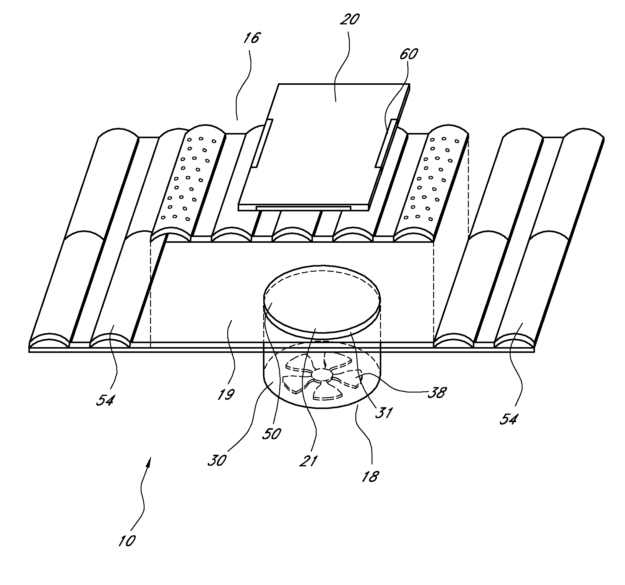
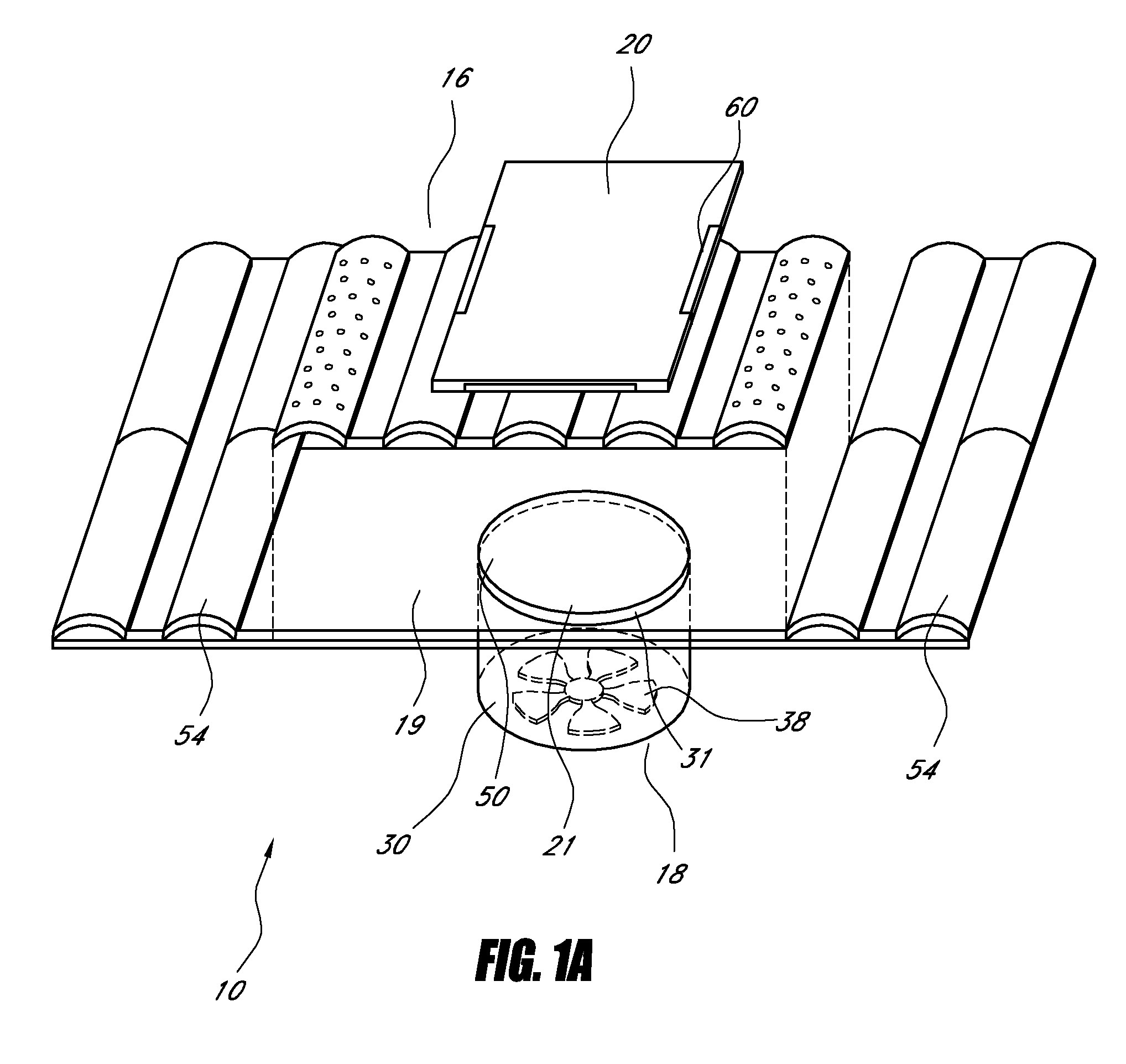
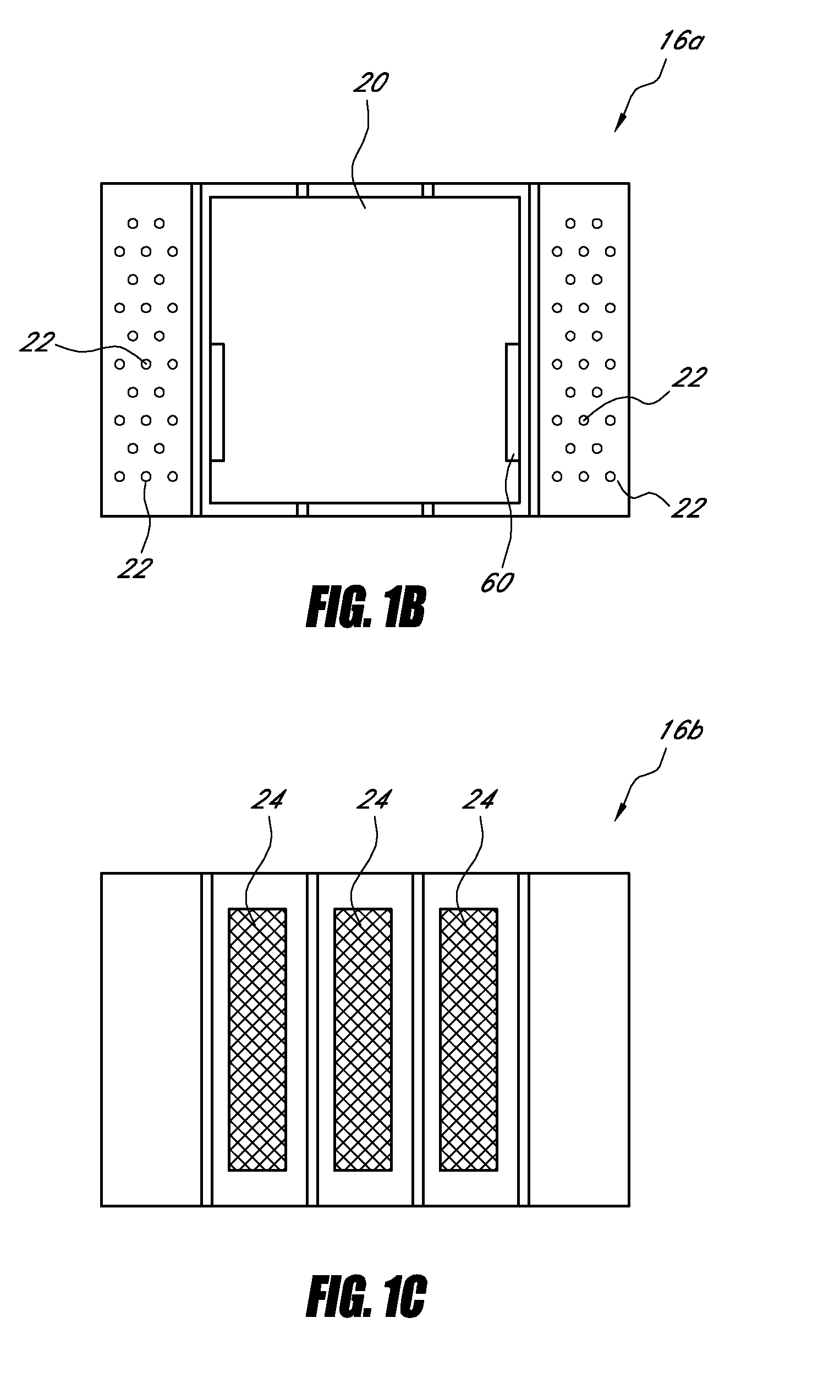
[0010]The presently disclosed embodiments seek to address the issues discussed above by utilizing a solar panel to power a fan associated with a roof vent system. The fan can be positioned in the attic space in order to accommodate fans with larger blades, capable of moving greater amounts of air. In one embodiment, the fan housing can be sized and shaped to simplify installation, such as by employing a substantially cylindrical housing that is generally free of protrusions. In other embodiments, the fan housing has a substantially frustoconical shape, facilitating the use of a relatively larger fan without necessitating a large hole in the roof. Some embodiments include a one-piece vent, which can be of particular utility in a composition roof. Other embodiments can utilize an upper vent having an appearance that mimics one or more tiles, for use in a tile roof.

[0011]In accordance...


PUM


Abstract

This application relates to ventilation systems, more particularly to a roof vent with one or more fan assemblies and/or an associated solar panel. The roof vent has an upper member including at least one opening that permits air flow between regions above and below the upper member. The vent further includes a lower member in fluid communication with the region below the upper member. The lower member includes a second opening permitting air flow between a region below the roof deck and the region below the upper member. The lower member further includes a fan configured to generate air flow through the second opening, wherein the fan resides in a fan housing positioned below the second opening.

Description

RELATED APPLICATIONS[0001]This application is a U.S. National Stage application, under 35 U.S.C. 371, of International Application No. PCT / US2009 / 035346, filed Feb. 26, 2009, which claims the benefit under 35 U.S.C. §119(e) to U.S. Provisional Application No. 61 / 067,280, filed Feb. 26, 2008, entitled “Roof Ventilation System,” the entire disclosure of which is hereby incorporated by reference herein.BACKGROUND OF THE INVENTION[0002]1. Field of the Invention[0003]This invention relates to ventilation systems, more particularly to active ventilation systems that can be used in a roof of a building.[0004]2. Description of the Related Art[0005]Ventilation of a building has numerous benefits for both the building and its occupants. For example, ventilation of an attic space can prevent the attic's temperature from rising to undesirable levels, which also reduces the cost of cooling the interior living space of the building. In addition, increased ventilation in an attic space tends to re...

Claims


Application Information

Patent Timeline
IPC IPC(8): F24F7/02F24F7/007
CPCF24F7/025E04D13/17
Inventor DANIELS, GREGORY S.
Owner DANIELS GREGORY S
Why Eureka
Try Eureka