Neurostimulation device and methods for controlling same

a neurostimulation device and control method technology, applied in electrotherapy, therapy, heart stimulators, etc., can solve problems such as system synergy, icds and pacemakers, and achieve the effect of limited nm energy conten

Inactive Publication Date: 2010-12-30
PACESETTER INC
View PDF5 Cites 26 Cited by
  • Summary
  • Abstract
  • Description
  • Claims
  • Application Information

AI Technical Summary

Benefits of technology

[0010]In another embodiment, a stimulation device is provided that is configured to be compatible with an implantable cardiac medical device (ICMD) that senses cardiac activity at frequencies within an ICMD sensing frequency range. The stimulation device includes a housing and a neuro lead configured to be coupled to the housing and to be located proximate to a neurostimulation site of interest. A neuro pulse generator, included in the housing, is configured to generate multi-polar neuro modulation (NM) pulses for delivery by the lead to the neuromodulation site of interest. The neuro pulse generator generates NM pulses utilizing an ICMD compatible waveform that comprises a plurality of the frequency components. The frequency components of the ICMD compatible waveform, in a range of less than 225 Hertz, have substantially limited NM energy content to avoid interference with sensing operation of the ICMD.

Problems solved by technology

This contraindication against use of both an ICMD and a NM device is due in part to certain interference that may be caused by the NM device upon the normal operation of the ICMD.
However, if an ICMD and neuromodulation device were both implanted, the systems may potentially be synergistic in their ability to treat certain patient cardiac disorders.
However, ICDs and pacemakers are contraindicated in these patients because of the concern for interference.

Method used


Image

  • Neurostimulation device and methods for controlling same
  • Neurostimulation device and methods for controlling same
  • Neurostimulation device and methods for controlling same

Examples


Embodiment Construction

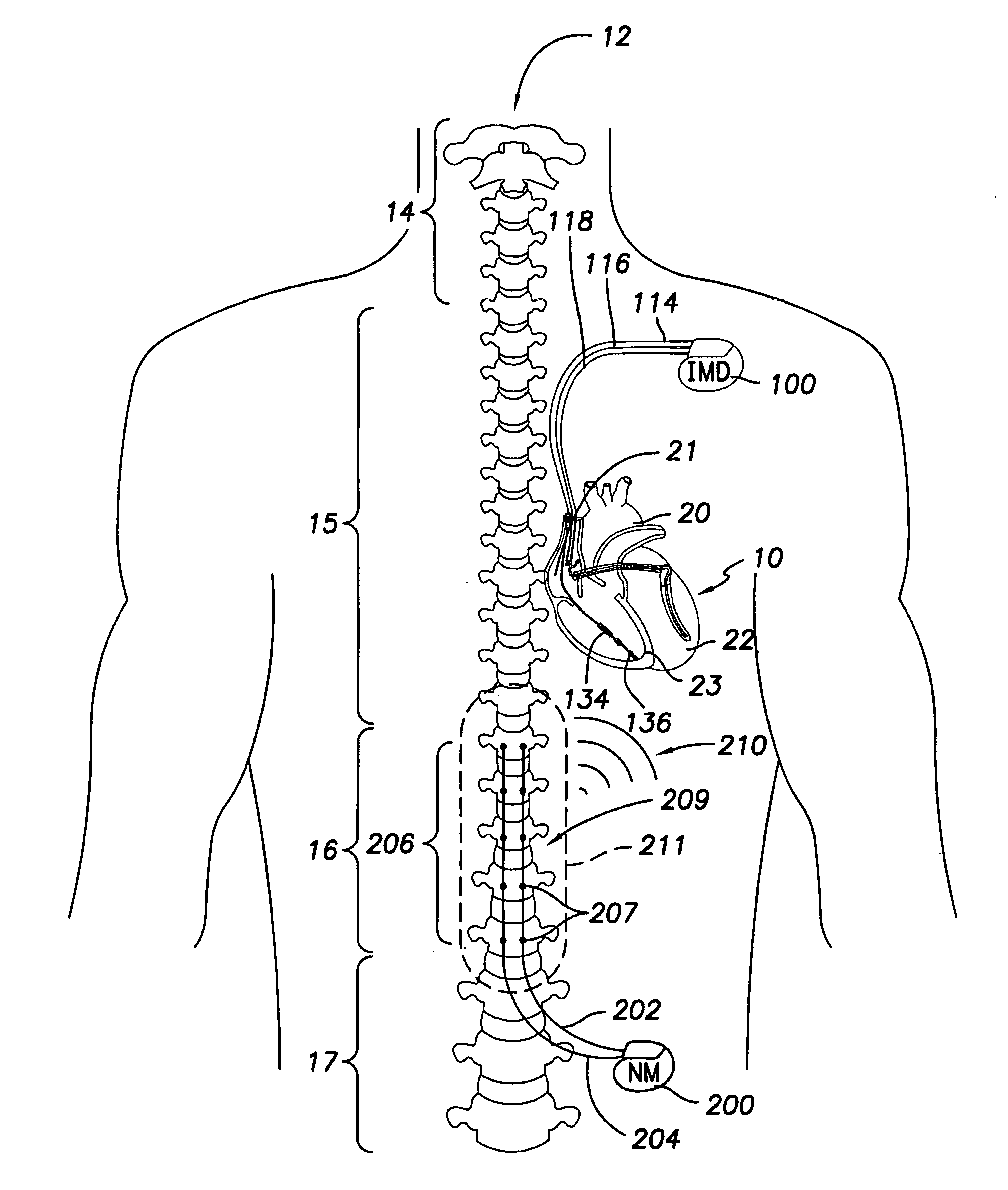
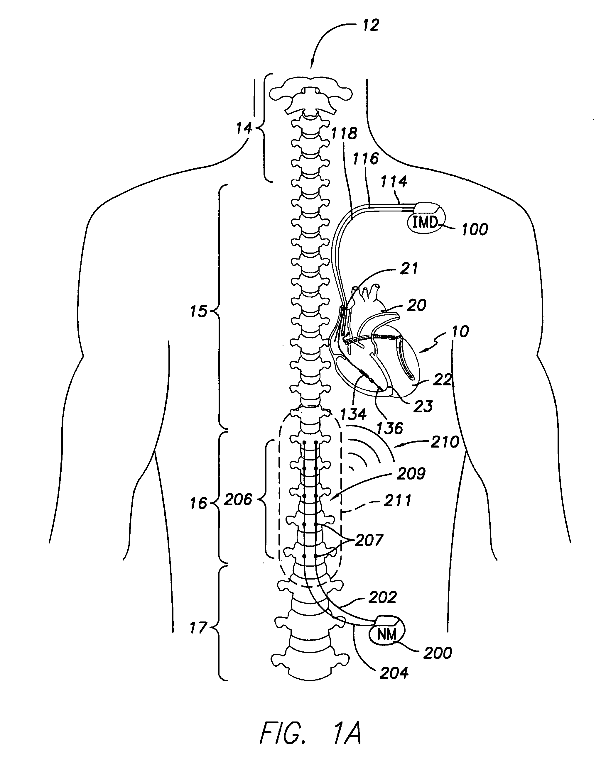
[0022]FIG. 1 illustrates a torso of a person who has been implanted with both an ICMD 100 and a neuromodulator device 200 in accordance with an embodiment. Within the torso, the heart 10 and spine 12 are illustrated. Regions 14-17 of the spine are noted for discussion purposes only, such as the cervical region 14, thoracic region 15, lumbar region 16 and pelvic region 17. Vertebrae within each of the regions 14-17 of the spine 12 will be discussed hereafter utilizing the terminology C1-C7 to refer to the seven vertebrae of the cervical region, T1-T12 to refer to the twelve vertebrae of the thoracic region, L1-L5 to refer to the five vertebrae of the lumbar, S1-S5 to refer to the five vertebrae of the sacral and tailbone to refer to the coccygeal vertebrae. Chambers of heart 10 are generally illustrated as the left atrium 20, right atrium 21, left ventricle 22 and right ventricle 23. Examples of NM devices 200 and NM programmers are disclosed in U.S. Pat. Nos. 7,486,995; 7,254,446; 7...


PUM


Abstract

A stimulation device that includes a housing, a neuro lead configured to be coupled to the housing and to be located proximate to a neurostimulation site of interest, a neuro pulse generator, in the housing, configured to generate multi-polar neuro modulation (NM) pulses for delivery by the lead to the neuromodulation site of interest and the neuro pulse generator generating the NM pulses utilizing a waveform, with the frequency components of the ICMD compatible waveform in a range of 0 to 225 Hz having substantially limited NM energy content to avoid interference with sensing operation of the ICMD. A method for managing a neuromodulation (NM) device to avoid interference with an implantable medical device (ICMD) providing an ICMD having electrodes configured based on ICMD sensing parameters that define an ICMD sensing frequency range, providing an NM device having NM electrodes to be located proximate a region of interest, the NM electrodes delivering NM pulses based on NM pulse parameters, setting at least one NM pulse parameter in a manner that limits an amount of NM energy content that propagates beyond an active area surrounding the site of interest within the ICMD sensing frequency range.

Description

FIELD OF THE INVENTION[0001]The present application generally relates to the field of neurostimulation devices and control methods for use therewith that avoid interference with the operation of an implantable medical device.BACKGROUND OF THE INVENTION[0002]Spinal cord stimulation (SCS) is a method for reducing pain in certain populations of patients. Neuromodulation devices have been proposed for use in a variety of SCS applications, such as for stimulation of the spinal cord, peripheral stimulation, brain stimulation and the like. SCS systems generally include an implantable pulse generator, lead wires and electrodes connected to the lead wires. The pulse generator is used to provide electrical stimulation pulses to an electrode array that is placed epidurally or surgically near a patient's spine or other area of interest. The electrodes within the array are placed at particular vertebrae along the spine depending upon the therapy sought, such as at the vertebrae labeled T2, T3, T...

Claims


Application Information

Patent Timeline
Patent Type & Authority Applications(United States)
IPC IPC(8): A61N1/08
CPCA61N1/36071A61N1/37A61N1/362A61N1/36082
Inventor BORNZIN, GENE A.POORE, JOHN W.BHARMI, RUPINDER
Owner PACESETTER INC
Why Eureka
Try Eureka