Method of Reducing Loading Failure for a Prosthetic Component

Active Publication Date: 2010-12-30
NUVASIVE
View PDF19 Cites 5 Cited by
  • Summary
  • Abstract
  • Description
  • Claims
  • Application Information

AI Technical Summary

Benefits of technology

[0016]According to the present invention there is provided a method of reducing loading failure for a p

Problems solved by technology

However although there have been many different artificial disks which have been described and tested, at this time they have all failed to reproduce the abilities of an invertebral disk.
Typical failings of previous artificial disks have included loosening or dislodgement of vertebral fixation, premature materials wear or structural failure, poor replication of normal or physiological spinal segmental motion and predisposition to the loss of normal neutral vertebral alignment.
Unfortunately these type of artifi

Method used


Image

  • Method of Reducing Loading Failure for a Prosthetic Component
  • Method of Reducing Loading Failure for a Prosthetic Component
  • Method of Reducing Loading Failure for a Prosthetic Component

Examples


Example

DETAILED DESCRIPTION OF THE DRAWINGS

[0071]According to a preferred embodiment of the present invention the instant centre of rotation (ICR) needs to be in the posterior portion of the upper end plate of the inferior vertebral body. Failure to achieve this position will prevent normal movement of the prosthesis and facet movement will be abnormal.

[0072]Little attention has so far been given to the statically loaded disc prosthesis—in other words, when it is not moving. This is the position in which the implant finds itself most of the time. In this position the neuromuscular control system recruits whatever muscles are necessary to maintain a static posture.

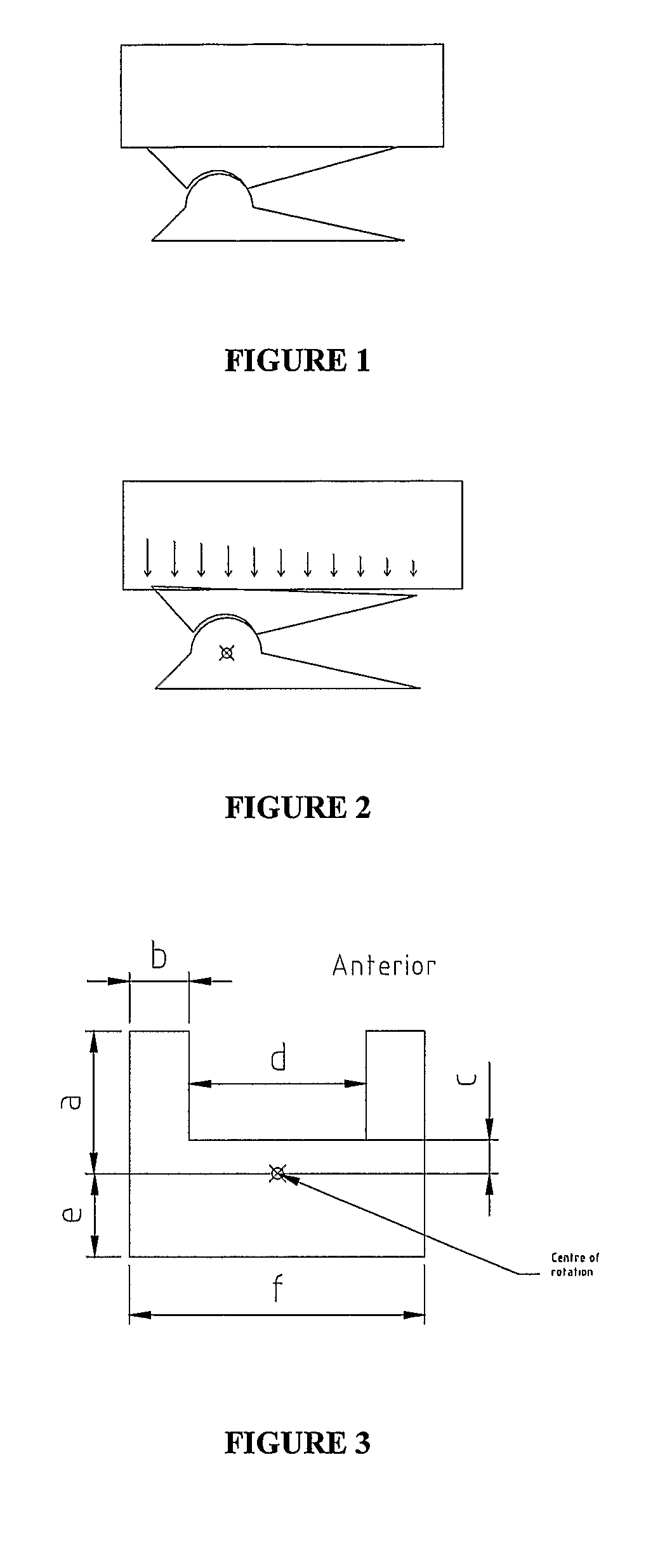
[0073]In a situation where a person is standing in a static position, the upper and lower end plates are parallel (FIG. 1).

[0074]If it is assumed that the applied load is distributed evenly across the surface of the implant it will have a uniform pressure distribution. If this were the case with the standard maverick footprint the...


PUM


Abstract

A method for reducing prosthetic loading failure including the steps of providing a prosthesis for a vertebral column comprising at least an upper part for attachment to an upper vertebrae and a lower part for attachment to a lower vertebrae, the upper part having a lower curved surface and the lower part having an upper curved surface, wherein the upper and lower curved surfaces have a centre of radius of curvature offset rearwardly with respect to a central vertical axis through the upper and lower vertebrae, and positioning the centroid of at least one of the upper and lower parts substantially on the same vertical axis of the centre of radius of curvature.

Description

FIELD OF THE INVENTION[0001]The present invention relates to a prosthesis for use in a skeletal structure. In one application the invention relates to a prosthesis for use as an artificial invertebral disk, predominantly but not exclusively for use in human spines.BACKGROUND OF THE INVENTION[0002]A human invertebral disk maintains a linkage between adjacent vertebrae of the vertebral column. It must fulfil a number of important functions including load bearing and dampening of impact forces. Furthermore, it must permit a complex pattern of movements and resist various stresses, pure or combined, in the sagittal, coronal and axial planes. Assisted by musco-ligamentous structures surrounding the spine, the invertebral disk must also help to maintain the normal alignment of the vertebrae of the spinal column.[0003]An ideal artificial disk replacement will accurately reproduce all the functions of the invertebral disk. However although there have been many different artificial disks whi...

Claims


Application Information

Patent Timeline
IPC IPC(8): A61F2/44
CPCA61F2/30734A61F2/4425A61F2002/30159A61F2230/0052A61F2002/30649A61F2230/0028A61F2002/30172A61F2/44
Inventor MCCOMBE, PETER
Owner NUVASIVE
Why Eureka
Try Eureka