Reducing power losses in a redundant power supply system

a power supply system and power loss technology, applied in the field of power supply management, can solve the problem of slow power supply startup times of soft start circuits

Inactive Publication Date: 2010-12-30
INTEL CORP
View PDF31 Cites 47 Cited by
  • Summary
  • Abstract
  • Description
  • Claims
  • Application Information

AI Technical Summary

Problems solved by technology

However, soft start circuits provide slow power supply startup times.

Method used


Image

  • Reducing power losses in a redundant power supply system
  • Reducing power losses in a redundant power supply system
  • Reducing power losses in a redundant power supply system

Examples


Embodiment Construction

[0018]Reference throughout this specification to “one embodiment” or “an embodiment” means that a particular feature, structure, or characteristic described in connection with the embodiment is included in at least one embodiment of the present invention. Thus, the appearances of the phrase “in one embodiment” or “an embodiment” in various places throughout this specification are not necessarily all referring to the same embodiment. Furthermore, the particular features, structures, or characteristics may be combined in one or more embodiments.

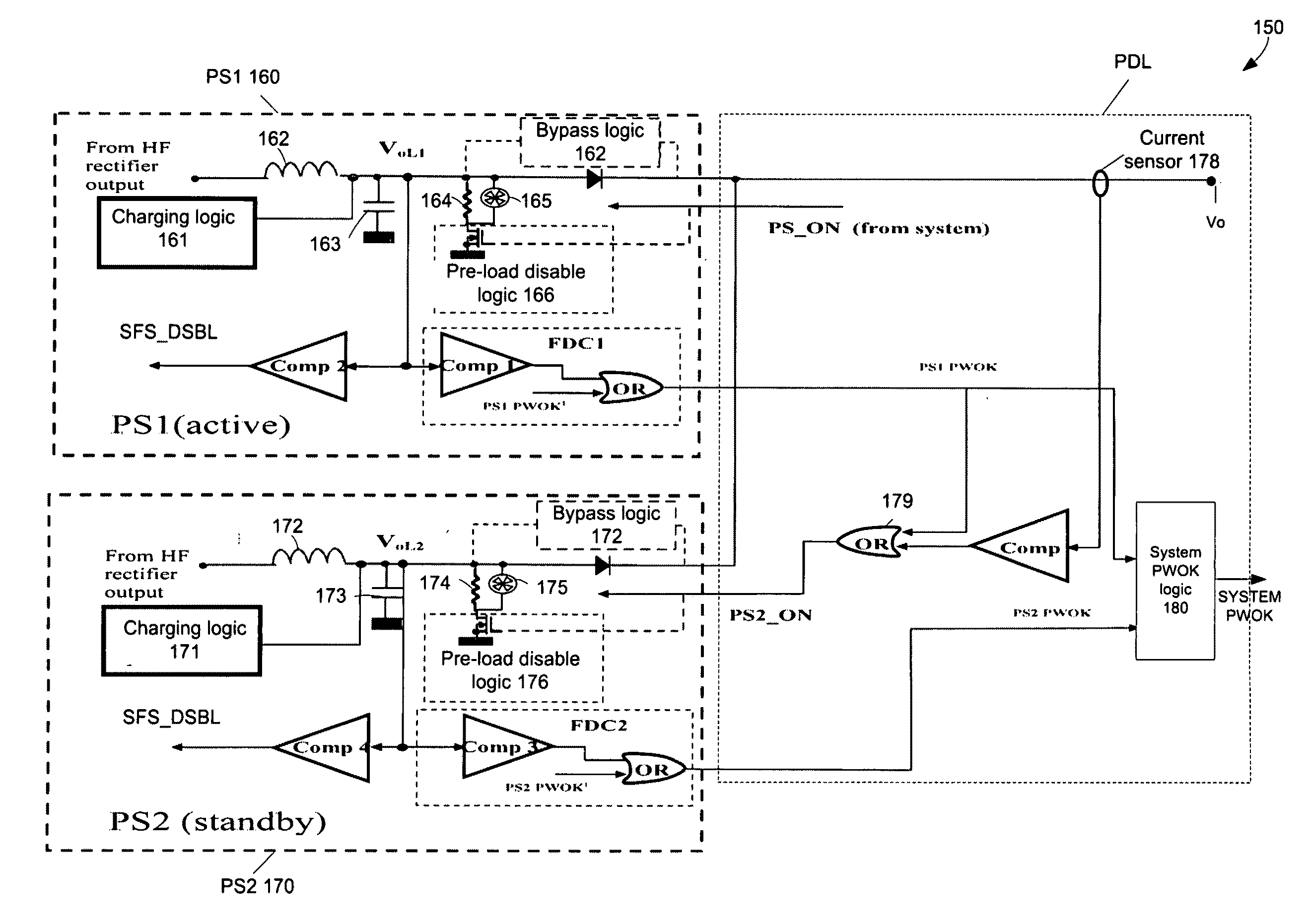
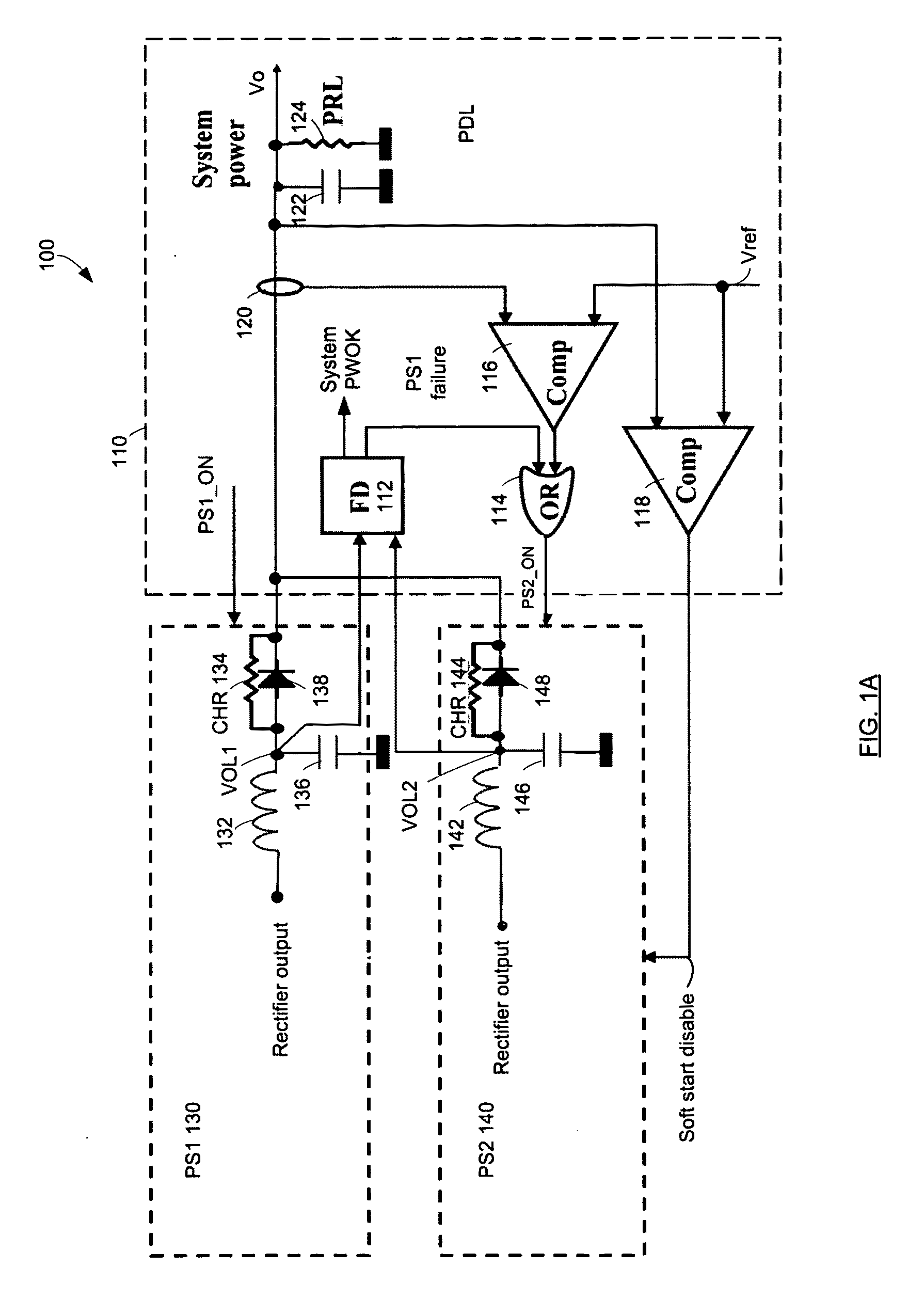
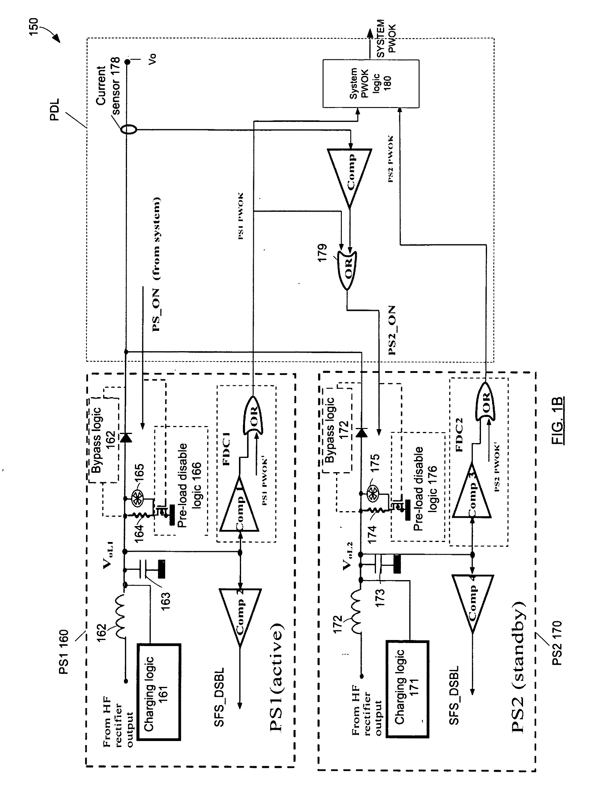
[0019]FIG. 1A depicts a functional block-diagram of a power supply system 100 in accordance with an embodiment of the present invention. System 100 may include power distribution logic (PDL) 110 that controls the power output of at least one power supply PS1130 and at least one redundant power supply PS2140. Additional power supplies can be added for control by PDL 110. PDL 110 controls whether one or both of PS1130 and PS2140 output power. Pow...


PUM


Abstract

A power supply system includes at least a first power supply module and at least one redundant power supply module. The at least one power supply module supplies power to an output terminal. The at least one redundant power supply module operates in a first state and in a second state. In the first state the second power supply module supplies power to the output terminal. In the second state the second power supply module provides standby power and operates in a burst mode (for example, such as a discontinuous conduction mode).

Description

RELATED APPLICATION [0001]This application is related to U.S. patent application Ser. No. 12 / 231,597 filed on Sep. 4, 2008 entitled “Power Management System” to William W. Carter, Brian J. Griffith, and Viktor D. Vogman.FIELD [0002]The subject matter disclosed herein relates generally to the field of power supply management.RELATED ART [0003]Many types of electronic devices use power supply systems to ensure that the proper output power is available for use. Many power supply systems require relatively large amounts of input and output currents when input power is first applied and power supply gets activated. Power supply systems typically use soft start circuits for the purpose of preventing destruction of circuitry due to a rush current occurring at start-up and preventing overshoot in the waveform of an output voltage as it rises. However, soft start circuits provide slow power supply startup times.[0004]Current power supply arrangements for computing platforms such as server pl...

Claims


Application Information

Patent Timeline
Patent Type & Authority Applications(United States)
IPC IPC(8): G06F1/26
CPCH02J9/005G06F1/263Y04S20/20Y02B70/30H02M7/04H02J9/061
Inventor VOGMAN, VIKTOR D.
Owner INTEL CORP
Why Eureka
Try Eureka