Heat Exchanger Leak Testing Method and Apparatus

a heat exchanger and leak detection technology, applied in the direction of measuring devices, instruments, structural/machine measurement, etc., can solve the problems of food products, thrown away, and general insatiable methods for detecting small particles

Active Publication Date: 2011-01-06
APV NORTH AMERICA
View PDF11 Cites 32 Cited by
  • Summary
  • Abstract
  • Description
  • Claims
  • Application Information

AI Technical Summary

Benefits of technology

[0015]Preferably, the test gas is hydrogen which may be mixed with an inert gas such as nitrogen to reduce the risk of an explosion. Where provided the tracer gas may be air.

Problems solved by technology

However, these methods are generally not satisfactory for detecting small faults such as fatigue cracks or corrosion pinholes that can occur in the heat exchanger plates.
While such faults may only allow a very small amount of cross-flow to occur, the resulting contamination of the food product is such that it must be thrown away and the heat exchanger disassembled to find and repair the fault.
This is wasteful of the food product and time consuming to carry out a repair, all of which adds to cost.

Method used


Image

  • Heat Exchanger Leak Testing Method and Apparatus
  • Heat Exchanger Leak Testing Method and Apparatus

Examples


Embodiment Construction

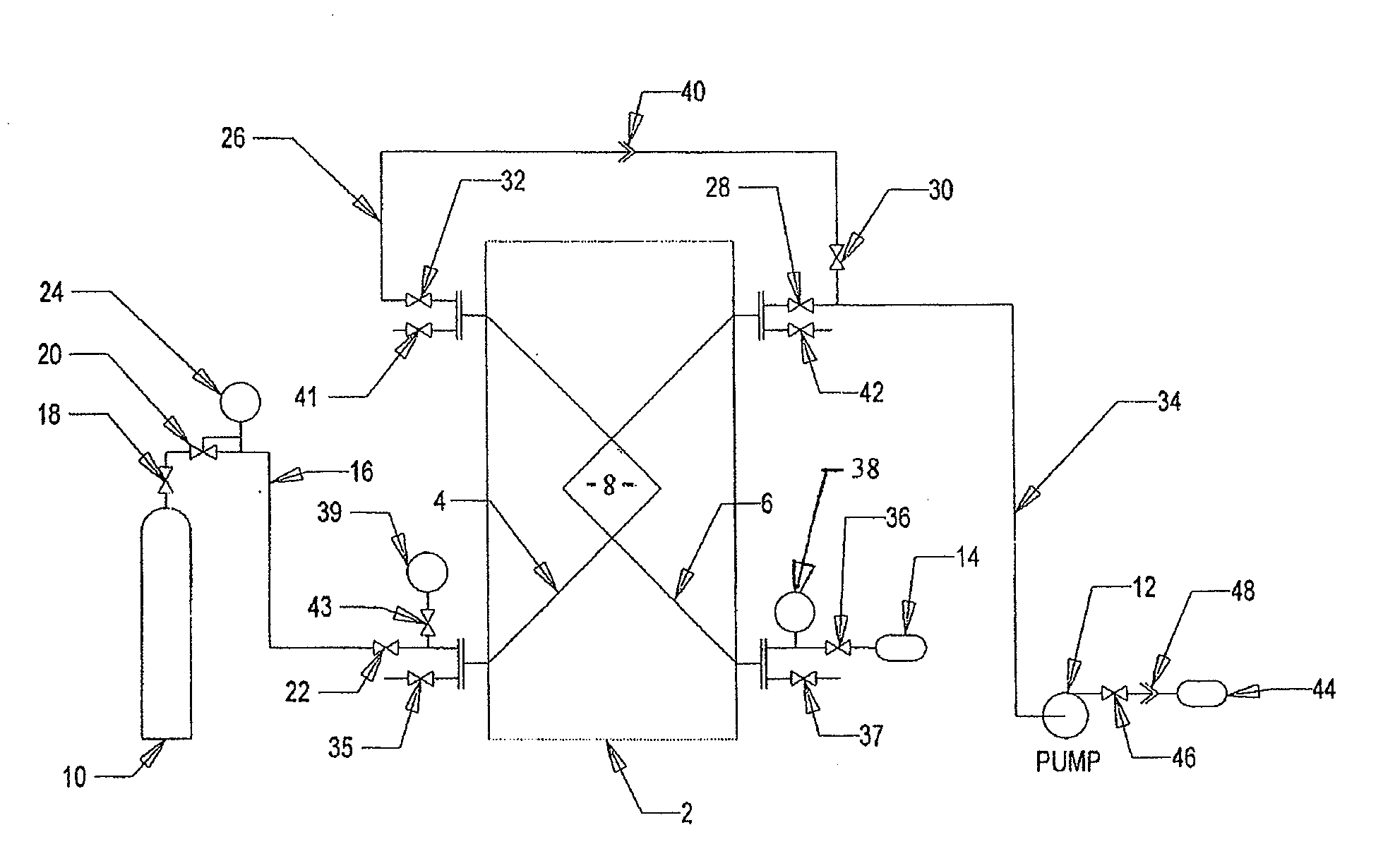
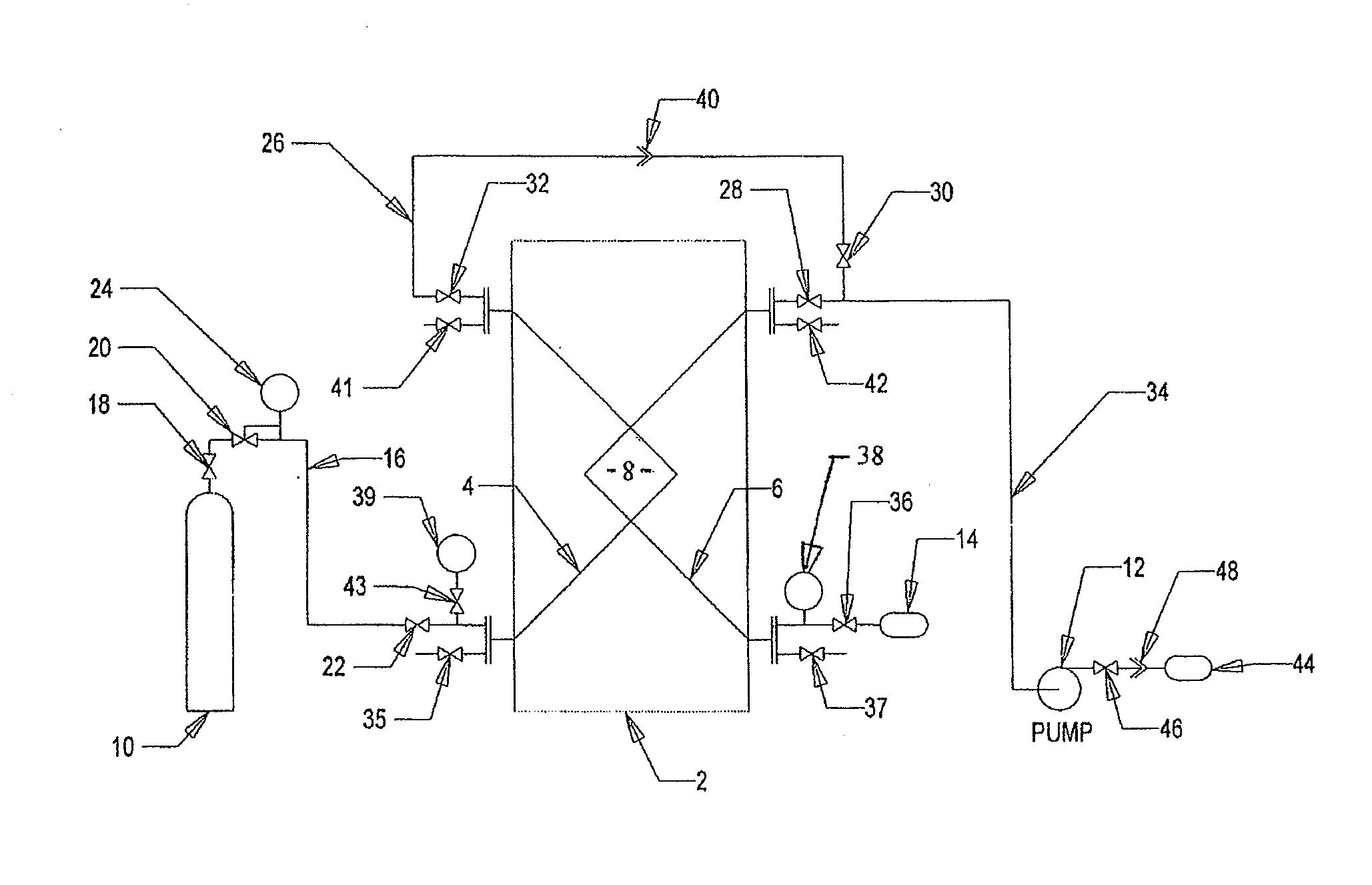
[0026]In the following description, the construction of the plate heat exchanger is not shown and described in detail as such heat exchangers are familiar to those skilled in the art and do not form an essential part of the invention which, as will be apparent from the following description, has application to all types and constructions of plate heat exchangers as well as other types of heat exchangers where separate flow paths for two fluids are arranged in close contact to facilitate heat transfer between the fluids.

[0027]Referring to the drawing, the two flow paths of a plate heat exchanger 2 are depicted as a donor side 4 and a receiving side 6 and are shown as being in close contact within a heat transfer section 8 of the heat exchanger. The terms “donor side” and “receiving side” are used hereinafter purely to distinguish between the flow paths for the purpose of clarity and are not descriptive of the heat exchanger 2 and are therefore not limiting on the scope of the inventi...


PUM


Abstract

A method for detecting the presence of a leak between two fluid paths of an assembled plate heat exchanger by evacuating one or both fluid paths to a low pressure, introducing a test gas to one of the fluid paths to create a pressure differential between the fluid paths, and testing for the presence of test gas in the second fluid path.

Description

CROSS-REFERENCE TO RELATED APPLICATIONS[0001]This application claims priority to and is a continuation of U.S. patent application entitled “Heat Exchanger Leak Testing Method and Apparatus,” filed Dec. 6, 2007, having Ser. No. 11 / 951,925, the disclosures of which is hereby incorporated by reference in its entirety.FIELD OF THE INVENTION[0002]This invention generally relates to heat exchangers for fluids. In particular, the invention relates to a method and apparatus for leak testing a heat exchanger, especially, but not exclusively, a plate heat exchanger.BACKGROUND OF THE INVENTION[0003]Heat exchangers typically comprise separate flow paths for two fluids arranged in close contact to facilitate heat transfer between the fluids thereby cooling the higher temperature fluid while simultaneously heating the lower temperature fluid as they flow through the heat exchanger. In plate heat exchangers the flow paths are commonly provided by a series of metallic plates packed vertically in se...

Claims


Application Information

Patent Timeline
Patent Type & Authority Applications(United States)
IPC IPC(8): G01M3/04
CPCG01M3/3227G01M3/228
Inventor KUMAR, HEMANTSHAW, JONATHAN GRAHAM
Owner APV NORTH AMERICA
Why Eureka
Try Eureka