Liquid-crystal display device

a display device and liquid crystal technology, applied in non-linear optics, instruments, optics, etc., can solve the problems of affecting the contrast and color of display images might significantly change depending on viewing angles, and the color and contrast of display images may largely change among different viewing angles

Active Publication Date:
View PDF3 Cites 6 Cited by
  • Summary
  • Abstract
  • Description
  • Claims
  • Application Information

AI Technical Summary

Benefits of technology

[0007]An object of the present invention is to provide a liquid-crystal display device, especially a VA-mode liquid-crystal display device having the advantage that its display image quality shows little variation under the different humidity conditions.

Problems solved by technology

Heretofore, one great weak point of liquid-crystal display devices was that contrast and color of those display images might significantly change depending on viewing angle.
Compared with IPS-mode liquid-crystal display devices, VA-mode liquid-crystal display devices have the advantage of high contrast, but have the problem that color and contrast of display images may largely change among different viewing angles.
Conventional liquid-crystal display devices have a problem that the contrast may greatly change depending on the humidity, and are desired to be improved in this point.

Method used


Image

  • Liquid-crystal display device
  • Liquid-crystal display device
  • Liquid-crystal display device

Examples


example 1

Construction of Liquid-Crystal Display Device

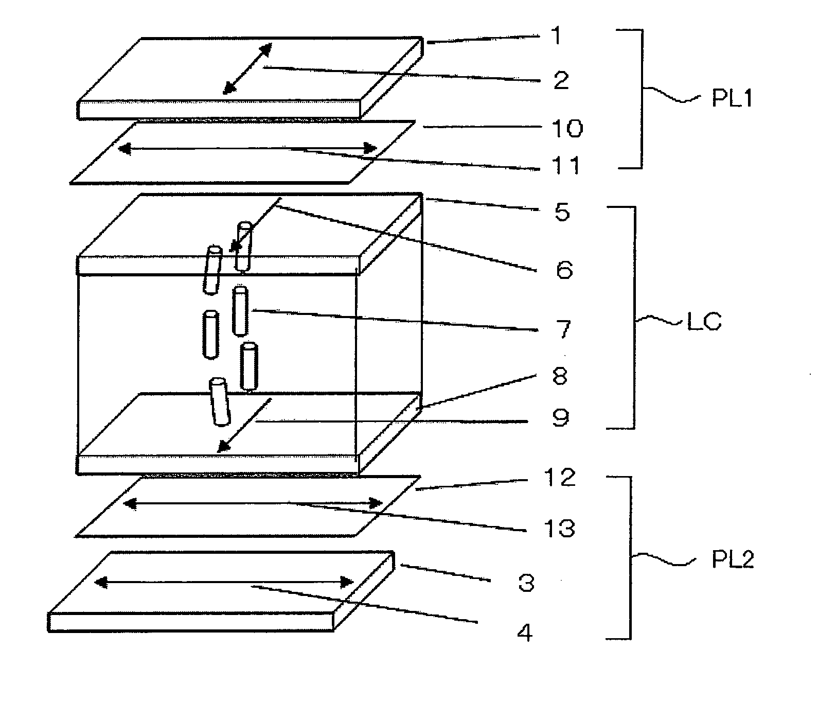
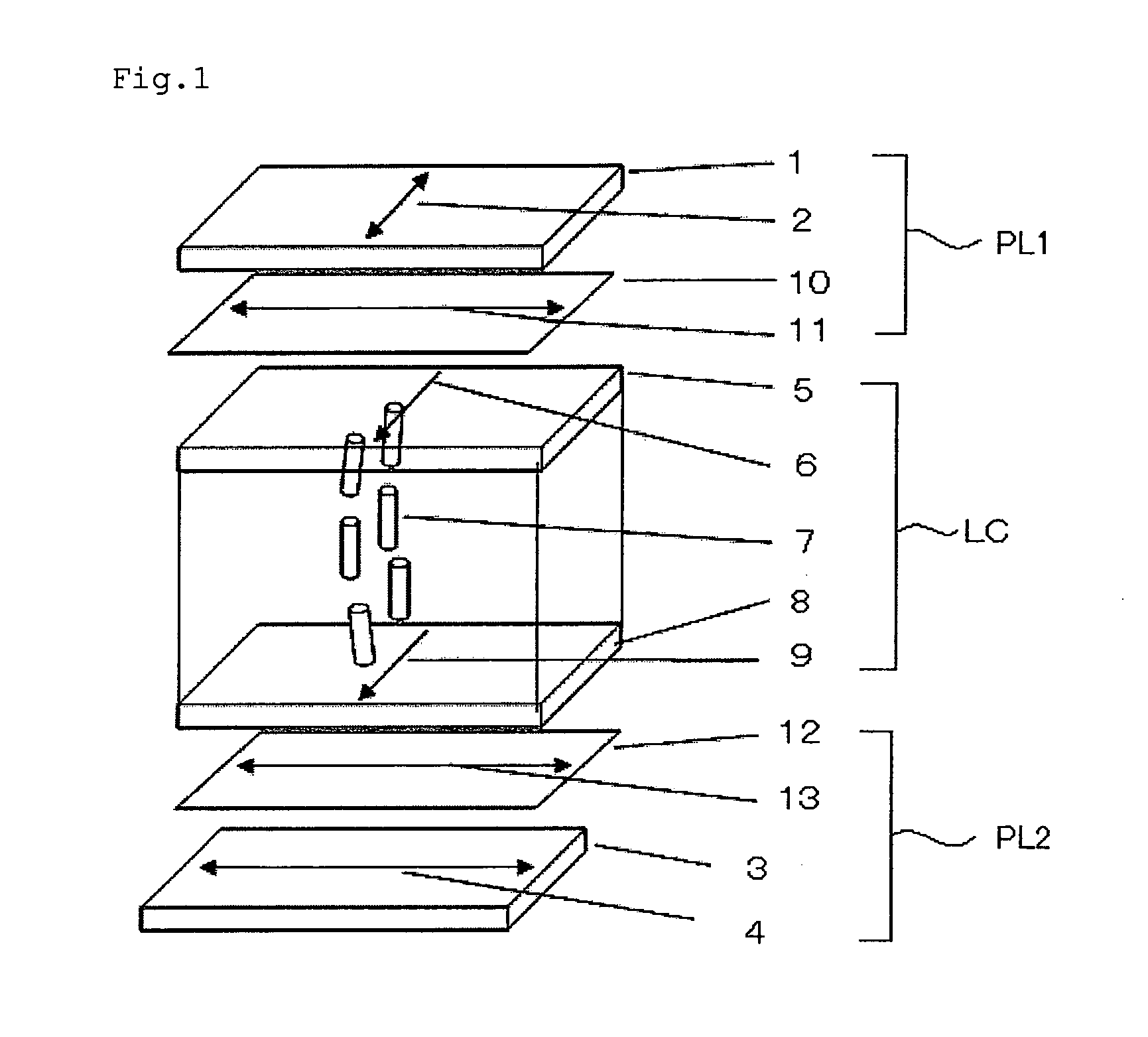
[0265]A VA-mode liquid-crystal display device having a constitution as in FIG. 1 was constructed. In FIG. 1, any one of the polarizing plates A to H was disposed as the upper polarizing plate PL1 in such a manner that the first retardation film could be on the side of the liquid-crystal cell LC, and any one of the polarizing plates I to N was disposed as the lower polarizing plate PL2 in such a manner that the second retardation film could be on the side of the liquid-crystal cell LC, and these were stuck one by one in that manner with an adhesive. In this, the upper polarizing plate PL1 is a polarizing plate on the side of the display panel, and the lower polarizing plate PL2 is a polarizing plate on the side of the backlight. These were disposed in a cross-Nicol configuration of such that the transmission axis of the polarizing plate on the viewers' side could run vertically and the transmission axis of the polarizing plate on the backl...

example 2

Construction of Liquid-Crystal Display Device

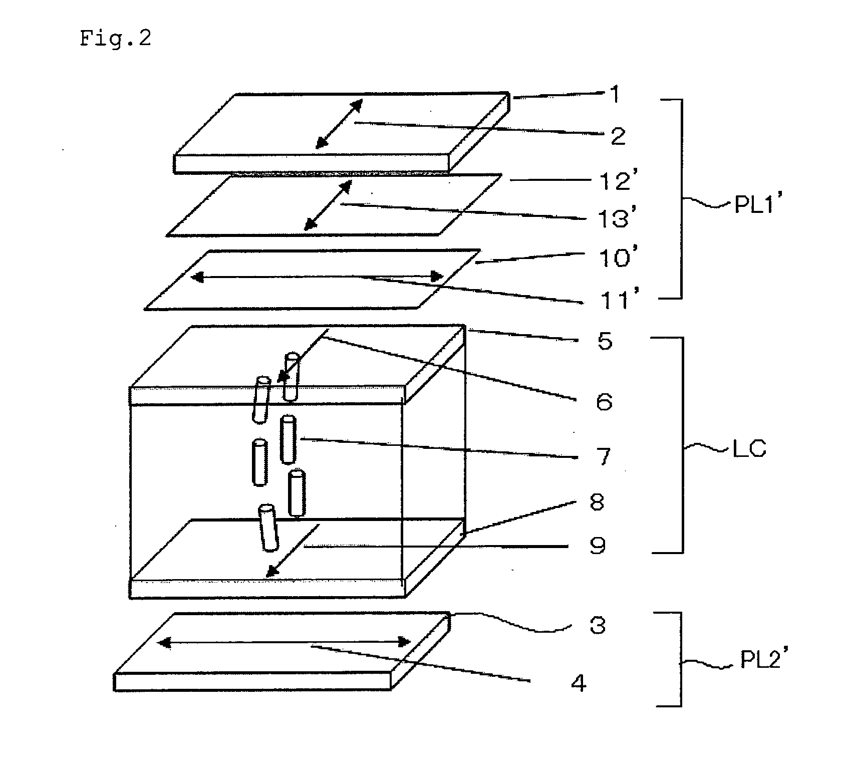
[0272]A VA-mode liquid-crystal display device having a constitution as in FIG. 2 was constructed. In FIG. 2, any one of the polarizing plate O and the polarizing plate P was disposed as the upper polarizing plate PL1′ in such a manner that the first retardation film 7 could be on the side of the liquid-crystal cell, and the polarizing plate Q was disposed as the lower polarizing plate PL2′, and these were stuck one by one in that manner with an adhesive. In this, the upper polarizing plate PL1′ is a polarizing plate on the side of the display panel, and the lower polarizing plate PL2′ is a polarizing plate on the side of the backlight. These were disposed in a cross-Nicol configuration of such that the transmission axis of the polarizing plate on the viewers' side could run vertically and the transmission axis of the polarizing plate on the backlight side could run horizontally. In that manner, LCD Nos. 301 and 302 were fabricated.

(Humidi...


PUM

PropertyMeasurementUnit
temperatureaaaaaaaaaa
thickness-aaaaaaaaaa
transmission axisaaaaaaaaaa

Abstract

A liquid-crystal display device comprising a liquid-crystal cell, a first polarizing element and a second polarizing element disposed on either side of the liquid-crystal cell respectively, a first retardation layer between the first polarizing element and the liquid-crystal cell, and a second retardation layer between the second polarizing element and the liquid-crystal cell, wherein a transmission axis of the first polarizing element is perpendicular to the slow axis of the first retardation layer; and a transmission axis of the second polarizing element is parallel to the slow axis of the second retardation layer; and the first retardation layer and the second retardation layer satisfy the formula (1) 0 nm<ΔRe1(548)−ΔRe2(548)≦50 nm.

Description

BACKGROUND OF THE INVENTION[0001]1. Technical Field of the Invention[0002]The present invention relates to a liquid-crystal display device, in particular to a VA-mode liquid-crystal display device.[0003]2. Related Art[0004]Liquid-crystal display devices have found wide application as power-saving and space-saving display devices. Heretofore, one great weak point of liquid-crystal display devices was that contrast and color of those display images might significantly change depending on viewing angle. However, in recent years, new-mode liquid-crystal display devices such as VA-mode and IPS-mode, of which display images show less viewing angle dependency than those of conventional liquid-crystal display devices, have been developed and put into use even for TVs that require high-quality display images.[0005]Compared with IPS-mode liquid-crystal display devices, VA-mode liquid-crystal display devices have the advantage of high contrast, but have the problem that color and contrast of d...

Claims


Application Information

Patent Timeline
Patent Type & Authority Applications(United States)
IPC IPC(8): G02F1/1335
CPCG02F1/1393G02F1/133634
Inventor FUKAGAWA, NOBUTAKANAKAYAMA, HAJIMETOYAMA, HIROFUMI
Why Eureka
Try Eureka