
Holographic image display systems

a technology of holographic image and display system, which is applied in the field of holographic image display system, can solve the problems of speck speckle in the displayed image, etc., and achieve the effect of reducing speckle in the imag

Inactive Publication Date: 2011-01-06
LIGHT BLUE OPTICS
View PDF6 Cites 104 Cited by
  • Summary
  • Abstract
  • Description
  • Claims
  • Application Information

AI Technical Summary

Benefits of technology

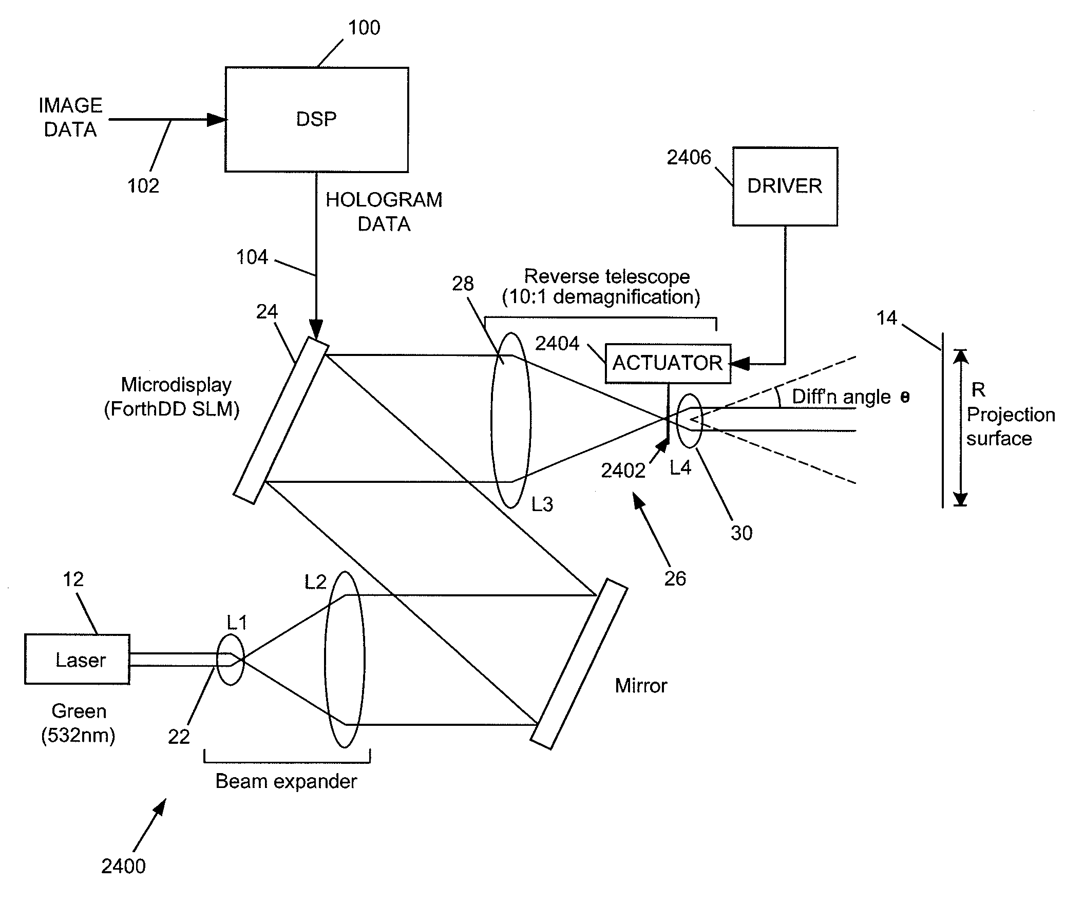
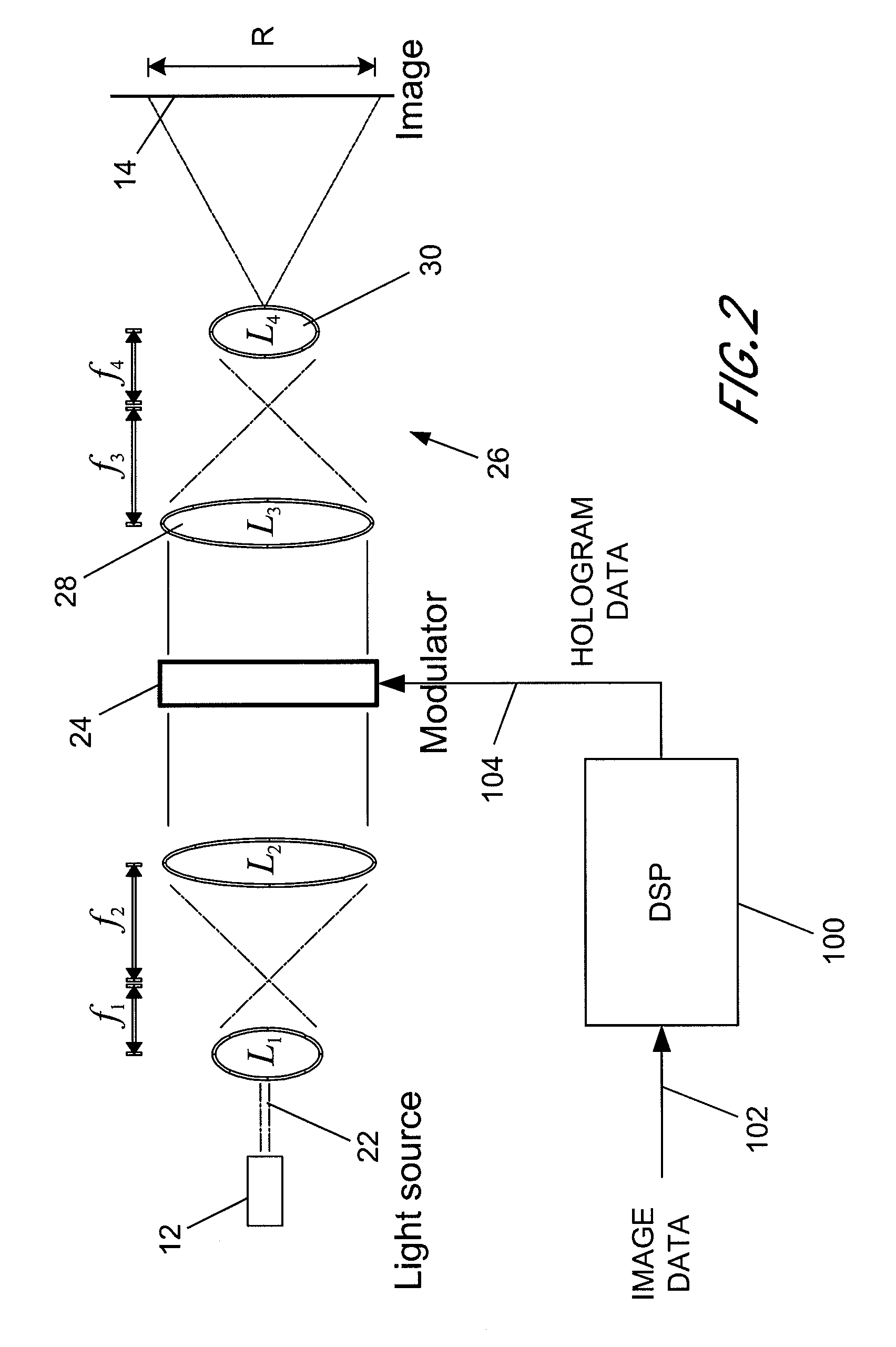
[0008]According to certain embodiments of the present invention there is therefore provided a holographic image display system for displaying an image holographically on a display surface, the system comprising: a spatial light modulator (SLM) to display a hologram; a light source to illuminate said displayed hologram; projection optics to project light from said illuminated displayed hologram onto said display surface to form a holographically generated two-dimensional image, said projection optics being configured to form, at an intermediate image surface, an intermediate two-dimensional image corresponding to said holographically generated image; a diffuser located at said intermediate image surface; and an actuator mechanically coupled to said diffuser to, in operation, move said diffuser to randomise phases over pixels of said intermediate image to reduce speckle in an image displayed by the system.

Problems solved by technology

Speckle is a problem in holographic image display systems, in particular those which display an image on a two-dimensional (though not necessarily planar) screen.
This is because images are generated using coherent light and when this falls on a surface, unevenness at the wavelength scale or greater causes interference in the eye of the observer and hence speckle in the displayed image.
Inter-pixel interference also results in an effect which has a visual appearance similar to speckle, although in this case the effect arises independently of the properties of the surface or the observer's eye.

Method used


Image

  • Holographic image display systems
  • Holographic image display systems
  • Holographic image display systems

Examples


Embodiment Construction

[0055]We have previously described, in UK patent application number 0512179.3 filed 15 Jun. 2005, incorporated in its entirety by reference herein, a holographic projection module comprising a substantially monochromatic light source such as a laser diode; a spatial light modulator (SLM) to (phase) modulate the light to provide a hologram for generating a displayed image; and a demagnifying optical system to increase the divergence of the modulated light to form the displayed image. Without the demagnifying optics the size (and distance from the SLM) of a displayed image depends on the pixel size of the SLM, smaller pixels diffracting the light more to produce a larger image. Typically an image would need to be viewed at a distance of several metres or more. The demagnifying optics increase the diffraction, thus allowing an image of a useful size to be displayed at a practical distance. Moreover the displayed image is substantially focus-free: that is the image is substantially in f...


PUM


Abstract

The invention relates to techniques for speckle reduction in holographic optical systems, in particular holographic image display systems. We describe a holographic image display system for displaying an image holographically on a display surface, the system including: a spatial light modulator (SLM) to display a hologram; a light source to illuminate said displayed hologram; projection optics to project light from said illuminated displayed hologram onto said display surface to form a holographically generated two-dimensional image, said projection optics being configured to form, at an intermediate image surface, an intermediate two-dimensional image corresponding to said holographically generated image; a diffuser located at said intermediate image surface; and an actuator mechanically coupled to said diffuser to, in operation, move said diffuser to randomise phases over pixels of said intermediate image to reduce speckle in an image displayed by the system.

Description

CROSS-REFERENCE TO RELATED APPLICATIONS[0001]This application is a continuation-in-part of International Application No. PCT / GB2008 / 051211, filed Dec. 19, 2008, designating the United States and published in English on Jul. 16, 2009 as WO 2009 / 087358 and incorporated in its entirety by reference herein, which claims the benefit of United Kingdom Appl. No. 0800167.9, filed Jan. 7, 2008 and incorporated in its entirety by reference herein.BACKGROUND OF THE INVENTION[0002]1. Field of the Invention[0003]This invention relates to techniques for speckle reduction in holographic optical systems, in particular holographic image display systems.[0004]2. Description of the Related Art[0005]Speckle is a problem in holographic image display systems, in particular those which display an image on a two-dimensional (though not necessarily planar) screen. This is because images are generated using coherent light and when this falls on a surface, unevenness at the wavelength scale or greater causes ...

Claims


Application Information

Patent Timeline
Patent Type & Authority Applications(United States)
IPC IPC(8): G03H1/32G02B5/32G03H1/08G02B27/48
CPCG02B5/02G02B26/06G02B27/48G03H1/2294G03H1/32G03H2001/2218H04N9/3197G03H2001/2297G03H2223/14G03H2227/03H04N9/3111H04N9/3161G03H2001/2271H04N5/7416
Inventor ROUTLEY, PAUL RICHARDCORBETT, ALEXANDER DAVIDCABLE, ADRIAN JAMESMCCAUGHAN, GARETH JOHN
Owner LIGHT BLUE OPTICS
Learn More