Anti-shock device for a timepiece control member

a technology of anti-shock device and control member, which is applied in the direction of shock protection arrangement, instruments, and exerting too much force on the control member, can cause the function to be affected too violently, parts have to be changed, and the timepiece case becomes complex and cumbersom

Active Publication Date: 2011-01-06
OMEGA SA
View PDF4 Cites 4 Cited by
  • Summary
  • Abstract
  • Description
  • Claims
  • Application Information

AI Technical Summary

Benefits of technology

[0004]It is an object of the present invention to overcome all or part of the aforecited drawbacks by proposing an

Problems solved by technology

In the case, particularly, of a chronograph mechanism, it is known that exerting too great a force on a control member, such as a push-button, can act too violently upon the functions associated therewith.
Thus, for example, it can happen that, on a crown or push-button used for operating a chronograph, the viole

Method used


Image

  • Anti-shock device for a timepiece control member
  • Anti-shock device for a timepiece control member
  • Anti-shock device for a timepiece control member

Examples


Embodiment Construction

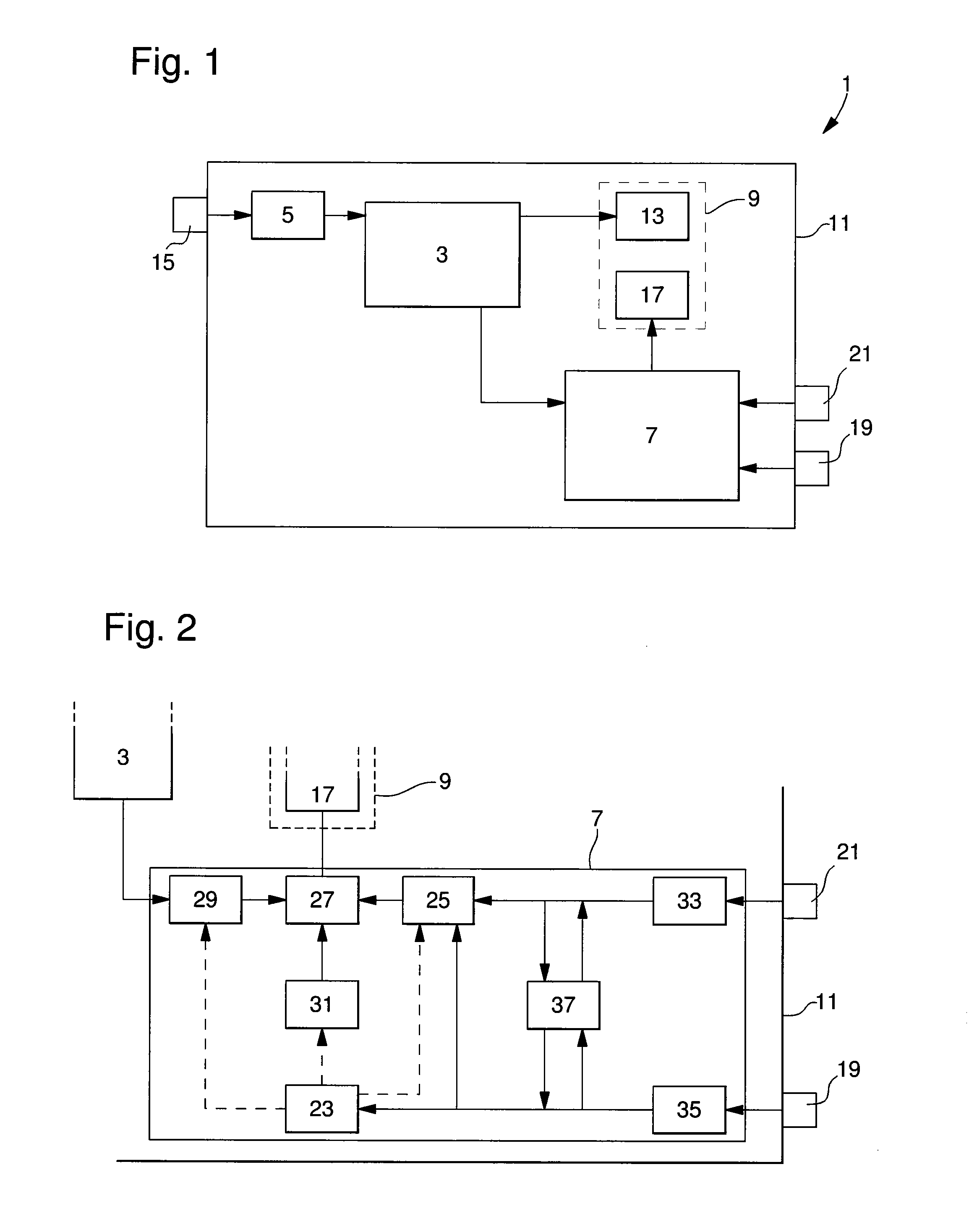
[0026]As illustrated in FIG. 1, the invention concerns a timepiece 1, whose case 11 includes a timepiece movement 3, a time-setting system 5, a chronograph mechanism 7 and a display system 9.

[0027]Timepiece movement 3, which is preferably mechanical, moves an indicator device 13 of display system 9, which may, for example, include a dial with an hour index and hands, which move above the dial and are connected to timepiece movement 3. The movement can be set via time-setting system 5, for example by operating a crown 15, which projects from case 11. As timepiece movement 3 is not protected by the invention, it will not be explained further here.

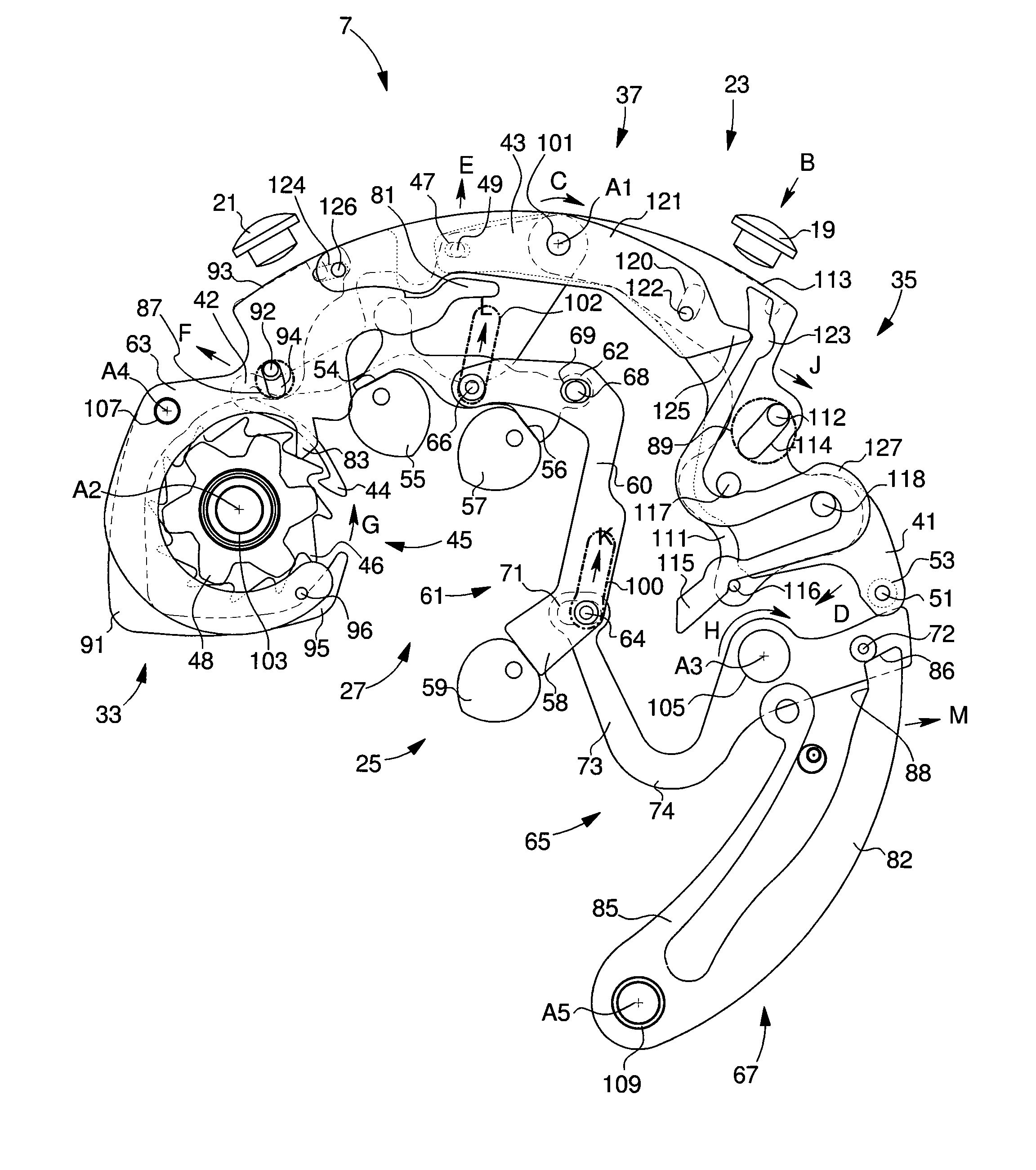
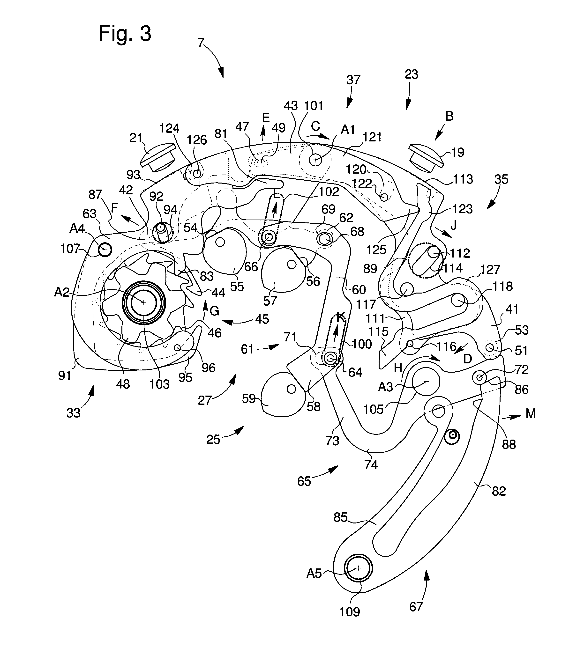
[0028]Two stage chronograph mechanism 7 moves a second indicator device 17, including at least one counter belonging to display system 9. Chronograph mechanism 7 is controlled by two control members 19, 21 and includes, as can be seen in FIG. 2, a control system 23, a reset device 25, a gear train device 27, a coupling device 29, an immobilis...


PUM


Abstract

Timepiece (1) including a case (11) in which systems (3, 5, 7, 9) are mounted for operating the timepiece, controlled by control members (15, 21, 19) that project from the case, at least one of the control members (15, 19, 21) cooperating with an anti-shock device (33, 35) mounted in the case (11) and including a main component (91, 111), which is moveably mounted relative to the case (11), characterized in that the main component (91, 111) includes a permanent mechanical connection with the part (63, 41) of each system (25, 23) to which the at least one control member is attached, which enables the component to be reversibly uncoupled from the at least one control member (15, 19, 21) when a force greater than a predetermined threshold is exerted on the at least one control member and in that the mechanical connection is of the sliding type, and includes a jumper spring (95, 115) elastically mounted relative to a pin (96, 116).

Description

FIELD OF THE INVENTION[0001]The invention relates to an anti-shock device for a member that controls a timepiece function and in particular a device of this type which can prevent any shock to said member activating the function associated therewith.BACKGROUND OF THE INVENTION[0002]In the case, particularly, of a chronograph mechanism, it is known that exerting too great a force on a control member, such as a push-button, can act too violently upon the functions associated therewith. Thus, for example, it can happen that, on a crown or push-button used for operating a chronograph, the violence of the force transmitted to the chronograph mechanism damages it, which may mean that parts have to be changed.[0003]To avoid such problems, it is known to protect push-buttons or crowns by using shoulders to border them or even using a fixed or removable frame, which completely or partially surrounds them. This prevents a shock from accidentally moving the push-buttons or crowns so as to prot...

Claims


Application Information

Patent Timeline
IPC IPC(8): G04B37/00
CPCG04F7/08G04B43/002G04F7/0804G04F7/0847
Inventor WYSSBROD, BAPTIST
Owner OMEGA SA
Why Eureka
Try Eureka