Tubulars storage device

Active Publication Date: 2011-01-13
ITREC BV
View PDF3 Cites 13 Cited by
  • Summary
  • Abstract
  • Description
  • Claims
  • Application Information

AI Technical Summary

Benefits of technology

[0019]in a first angular position of the rotary latch members shaft all latch members on the shaft extend in the path of displacement of tubulars, thereby prohibiting displacement of the tubulars along th

Problems solved by technology

As the finger members are often mounted at a great height (in some instances 90 feet above the d

Method used


Image

  • Tubulars storage device
  • Tubulars storage device
  • Tubulars storage device

Examples


Example

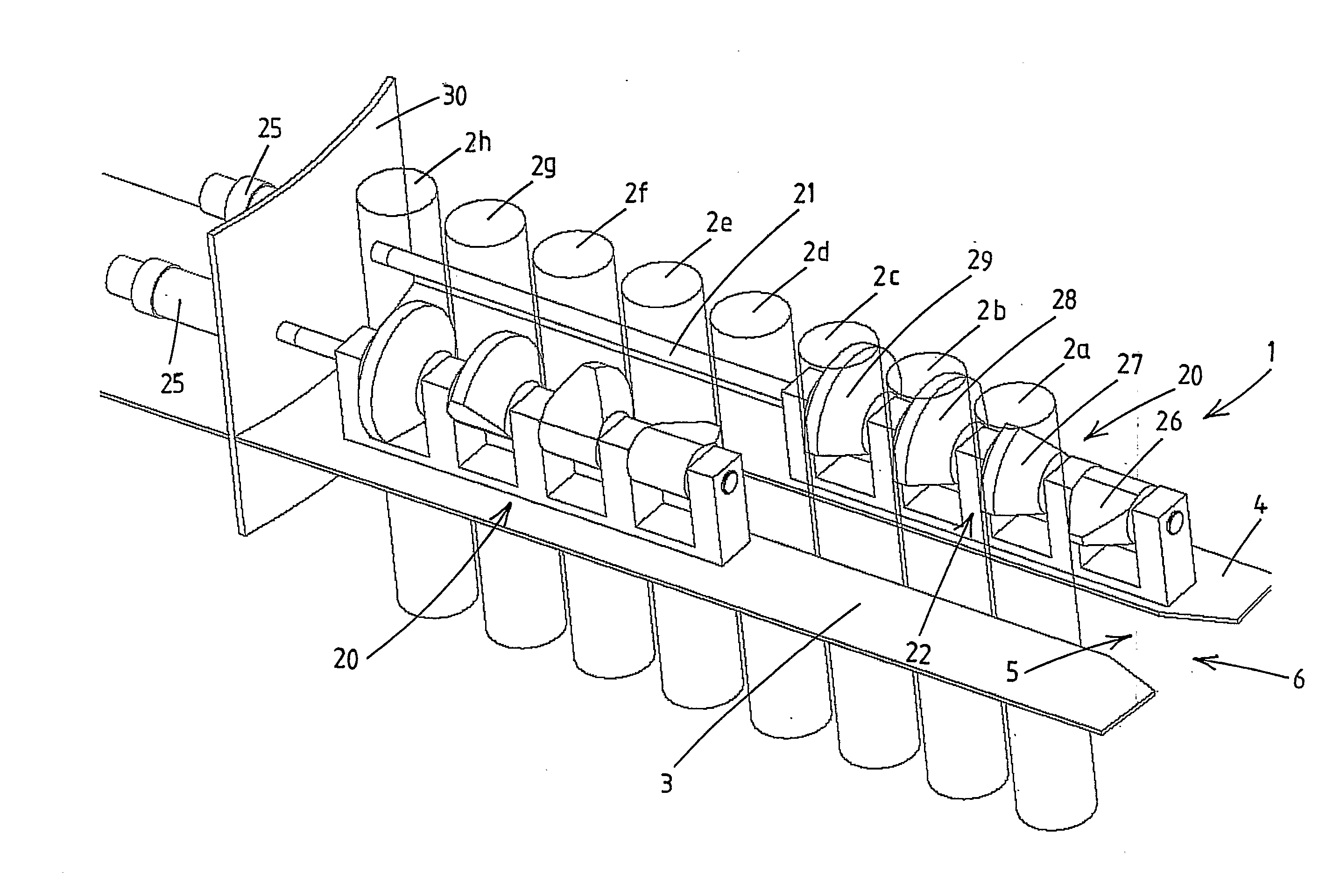
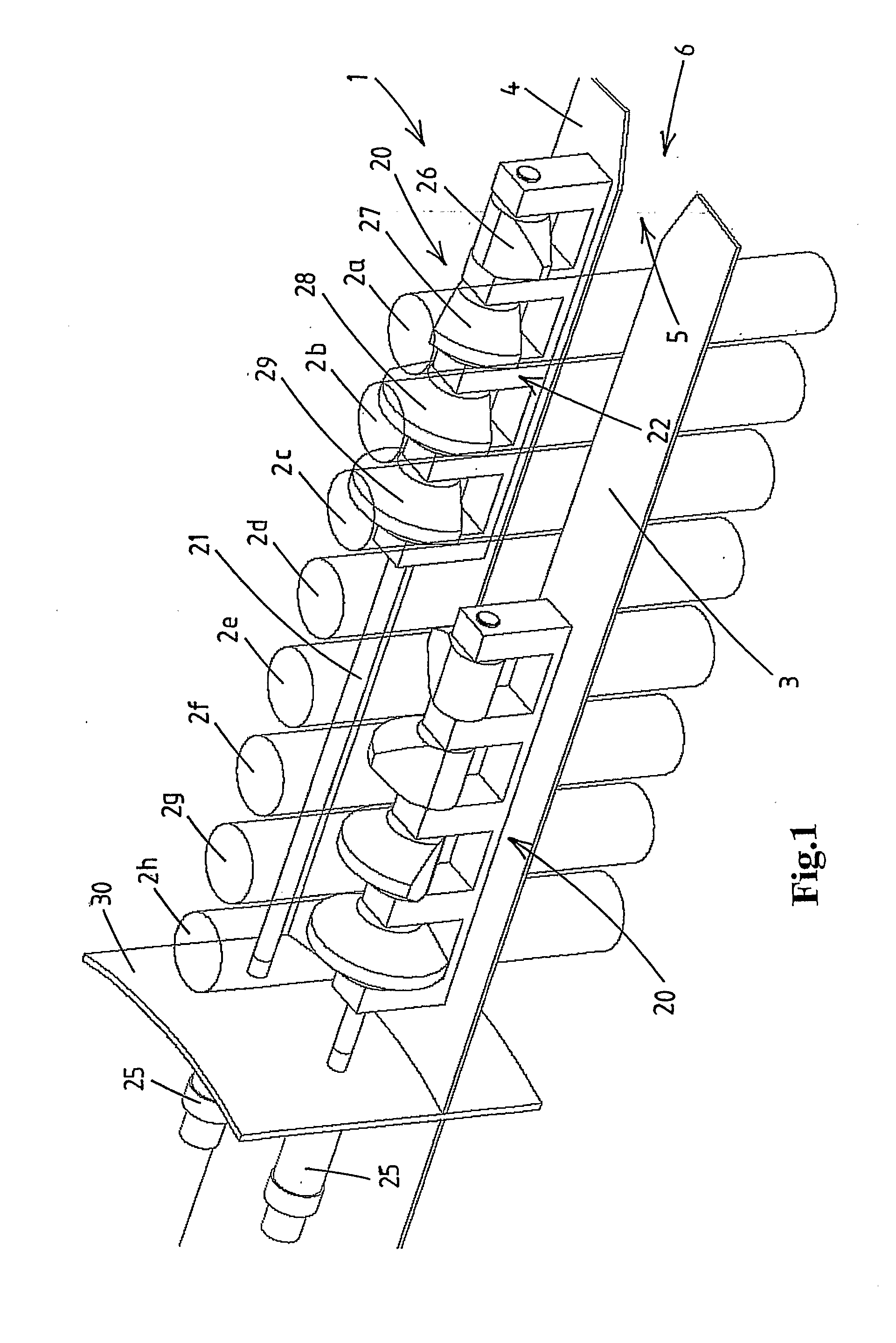
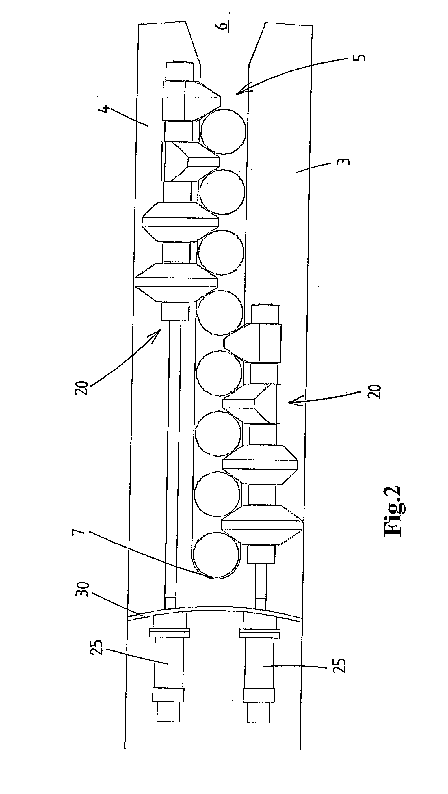
[0034]Referring to FIGS. 1-5 a preferred embodiment of a tubulars storage device 1 according to the invention for storing a plurality of tubulars 2a-h will be explained in detail. As mentioned above the term “tubulars” is a known term in the oil and gas industry and is intended to cover all tubular products used for well drilling and other well related activities.

[0035]In the examples shown herein it is assumed that the tubulars 2a-h are stored in vertical position, but the storage device according to the invention is also suited for other orientation of the tubulars, e.g. horizontal storage.

[0036]The tubulars 2a-h may be suspended in vertical position from the storage device, e.g. by each tubular having a larger diameter head (e.g. a connector head) which engages on the storage device, e.g. on suspension members mounted at a higher level than the finger members 3,4.

[0037]In this example it is assumed that the lower ends of the vertically arranged tubulars are resting on a support s...


PUM


Abstract

A tubulars storage device for storing a plurality of tubulars which has a slot forming a path of displacement for tubulars allowing to place tubulars at respective storage positions distributed along the slot as well as removal of said tubulars from the slot. The device includes a rotary latch members shaft, which is mounted substantially parallel to the slot, and a drive connected to the rotary latch members shaft, said drive being adapted to effect controlled angular rotation of the latch members shaft. A plurality of latch members are mounted on the latch members shaft so as to rotate with the latch members shaft and are arranged at spaced apart locations along the latch members shaft.

Description

FIELD OF THE INVENTION[0001]The present invention relates to a tubulars storage device for storing a plurality of tubulars. In the oil and gas well drilling industry numerous types of piping, referred to generally as “tubulars”, are used. Tubulars include drill pipes, casing pipes, and other connectable (e.g. by screwthread) oil and gas well structures. Long “strings” of joined tubulars, e.g. drill strings or casing stands, are typically used to drill a wellbore and to prevent collapse of the wellbore after drilling.[0002]A common tubular storage device for tubulars in the oil and gas industry is referred to as “a fingerboard”. Other known storage devices for tubulars in the oil and gas industry are referred to as “setbacks”, “setback drums”, “pipe racks”, “pipe rackers”, etc.BACKGROUND OF THE INVENTION[0003]Tubulars storage devices, such as fingerboards, typically include a slot delimiting structure, e.g. spaced apart finger members, that define a slot capable of receiving a plural...

Claims


Application Information

Patent Timeline
IPC IPC(8): E04H12/00E21B19/14
CPCE21B19/14
Inventor ROODENBURG, JOOPHORAK, MICHALKROMDIJK, HARMEN JAN
Owner ITREC BV
Why Eureka
Try Eureka