Rotary cutter for mower

a rotary cutter and mower technology, applied in metal working apparatus, agriculture tools and machines, agriculture, etc., can solve the problems of inconvenient and troublesome mowing procedures, inability to easily carry out production/processing, and loss of components, so as to facilitate and quickly insert the cord, fast and positively wind up the cord to the reel, and simple production/processing

Active Publication Date: 2011-01-13
STARTING IND CO LTD
View PDF7 Cites 8 Cited by
  • Summary
  • Abstract
  • Description
  • Claims
  • Application Information

AI Technical Summary

Benefits of technology

[0015]According to a rotary cutter for a mower related to the present invention, in which the reel and the pressing body are integrally constructed, there is no possibility of losing associated components of a reel and other components when replacing a cord, and a concave-grooves fitting method has been adopted instead of a conventional insertion method as a cord-winding mechanism to the reel, thus the cord is wound by inserting and fitting itself to the concave grooves for inserting the cord provided in the reel. As a result, it is possible to easily and quickly insert the cord and also quickly and positively wind up the cord to the reel. In accordance with a further aspect, structurally, there is a small number of items of components, its production / processing is simple, and the production cost is inexpensive.
[0016]According to a rotary cutter for a mower in which the reel and the pressing body are separately constructed, like the above-mentioned rotary cutter for a mower, there is no possibility of losing associated components of a reel and other components when replacing a cord, and structurally there is a small number of items of components, so its production / processing is simple, and the production cost is inexpensive. Furthermore, especially when replacing a cord, it is possible to wind up the cord to the reel easily, quickly and positively, since the pressing body can be rotated without moving up and down. Still further, like the above-mentioned rotary cutter for a mower, it is possible to insert the cord easily and quickly to the reel by the addition of an advantageous effect of concave grooves for inserting the cord.
[0017]According to the above-mentioned two kinds of the rotary cutter for a mower of the present invention, it is possible to prevent the cord from uplifting / deviating from the reel and to stably and positively wind up the cord when winding up the cord to the reel, by providing projections for preventing from deviating the cord on the inner wall of the concave grooves for inserting the cord, or, by forming a shape of openings of the concave grooves for inserting the cord into a hook / aduncate shape.

Problems solved by technology

However, by such a way, it is very troublesome and inconvenient to carry out such procedures during mowing.
Moreover, when the rotary cutter is disassembled and the reel is taken out, it has been feared that these components may be lost since associated components of the reel and other components are taken out at the same time.
However, for example, in the case of a rotary cutter described in Patent document 1, there are some drawbacks that it is necessary to provide a cord through-hole formed between an outer circumferential surface and an inner circumferential surface of a cylindrical body of a reel (a cord-winding part) of a reel, the cord through-hole being perpendicular to an axis of rotation without providing on the inner circumferential surface, so that top and bottom positions of its cord insertion opening and a guiding hole can be on the same horizontal plane.
As a result, production / processing cannot be easily carried out in order to form its cord through-hole and the guiding hole.
Therefore, the production cost of such a rotary cutter can be relatively high.
Therefore, such a rotary cutter has some drawbacks that the structure of the reel is relatively complicated; a lot of time and effort are needed for its production / processing; and the production cost of such a rotary cutter can be relatively high.
Therefore, the rotary cutter of Patent document 3 has some drawbacks that the structure of the reel is more complicated; much more time and effort are needed for its production / processing; and the production cost of such a rotary cutter can be higher.
Further, in the case of the conventional rotary cutter as claimed in Patent documents 1-3, there is a common drawback that the insertion / conduction operation of the cord when the cord is wound on the reel requires time and effort.

Method used


Image

  • Rotary cutter for mower
  • Rotary cutter for mower
  • Rotary cutter for mower

Examples


first embodiment

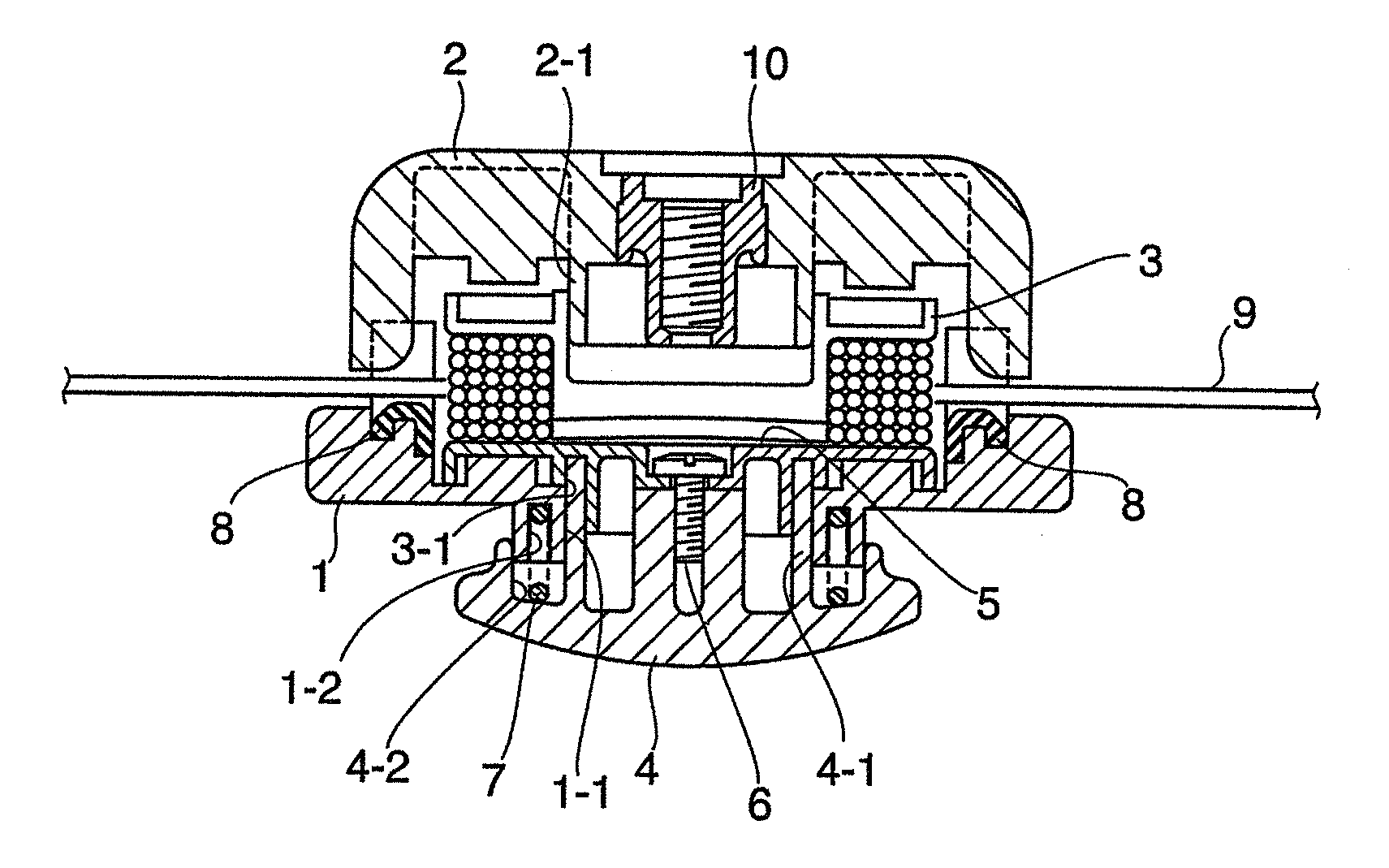
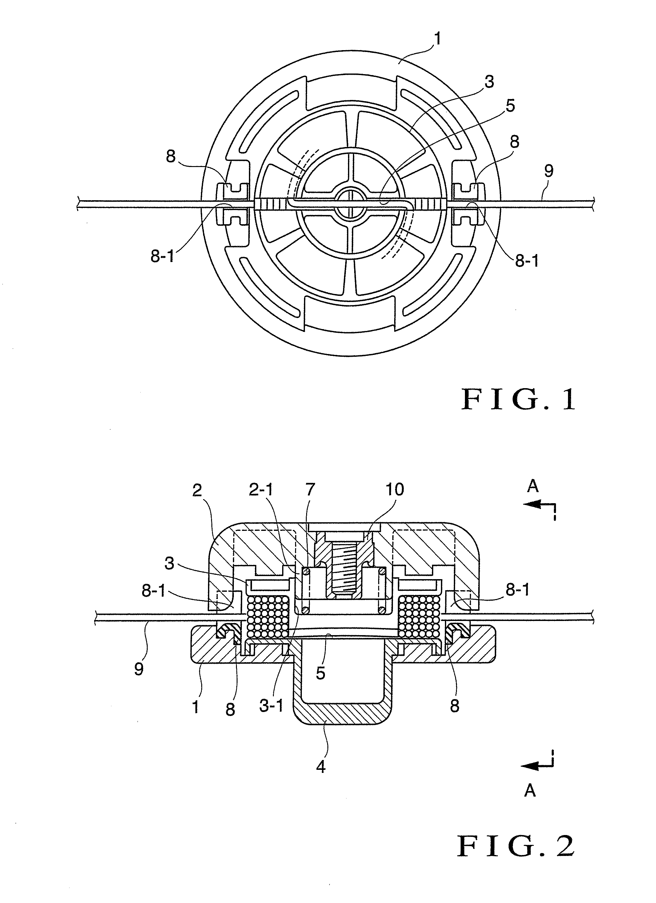
[0038]According to the rotary cutter for a mower having constitutions shown in the above-mentioned FIG. 4, in replacing a cord when it is worn out, like the rotary cutter of the above first embodiment, both the spring 7 and the cover 2 detachably engaged with the reel 3, are removed, and then a portion which is located in the central part of a long and new cord having a desired length, is fitted and placed to the concave grooves 5 for inserting a cord formed to the empty reel 3 which is engaged with the case 1 and to the concave grooves 8-1 on the cord guide 8 formed in the same straight line with this concave grooves 5 for inserting the cord from the top of these grooves, while making both ends of the cord respectively stick out from the cord guides only at a suitable length. In such conditions, a portion of the pressing body 4, which is connected to the reel 3 with the screw, is gripped and the reel is rotated manually so that the cord 9 can be wound to the reel 3.

[0039]Also, in r...

second embodiment

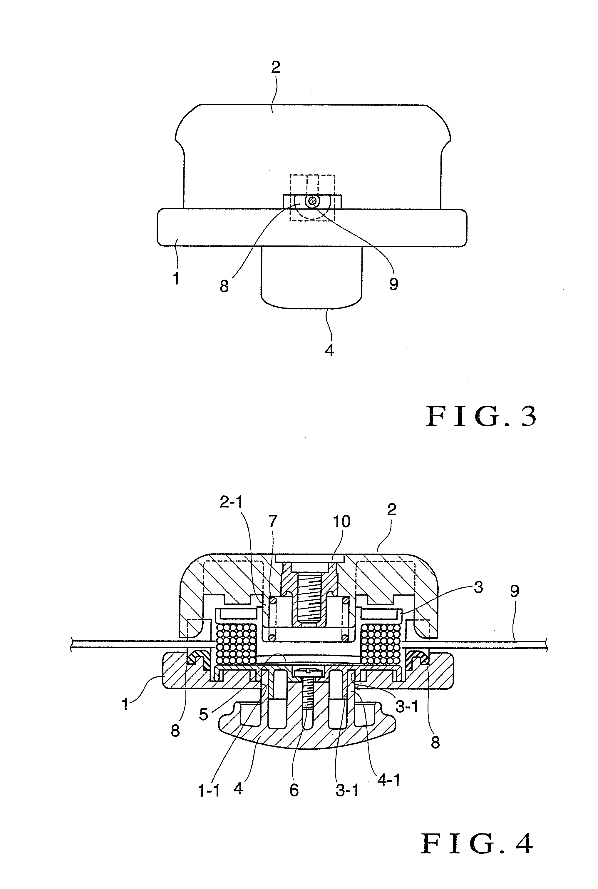
[0041]According to the rotary cutter for a mower having constitutions shown in the above-mentioned FIG. 5, in replacing a cord when it is worn out, like the rotary cutter of the above second embodiment, the cover 2 detachably engaged with the reel 3 is removed, and then a portion which is located in the central part of a long and new cord having a desired length, is fitted and placed to the concave grooves 5 for inserting a cord formed to the empty reel 3 which is engaged with the case 1 and to the concave grooves 8-1 on the cord guide 8 formed in the same straight line with this concave grooves 5 for inserting the cord from the top of these grooves, while making both ends of the cord respectively stick out from the cord guides only at a suitable length. In such conditions, a portion of the pressing body 4, which is connected to the reel 3 with the screw, is gripped and the reel is rotated manually so that the cord 9 can be wound to the reel 3.

[0042]In replacing a cord of the above-...


PUM


Abstract

A rotary cutter for a mower has a cord for cutting grass and the like by rotating itself; a reel for housing the cord and feeding the cord while intermittently rotating; a case for housing the reel; a cover for covering the case; and a pressing body protruding from the case. The pressing body is axially movable by being pressed, and intermittently rotating the reel. The reel and the pressing body are integrally constructed. Concave grooves for inserting the cord are provided in the reel in a radial direction and the cord is wound by fitting it to the concave grooves.

Description

BACKGROUND OF THE INVENTION[0001]1. Field of the Invention[0002]The present invention relates to a rotary cutter for a mower used for mowing grass, lawn, and the like with a cord (principally made of nylon) extending in a radial direction of a case which is rotationally-driven by power of a motor or the like by way of an axis of rotation.[0003]2. Description of the Related Art[0004]As this type of rotary cutter, it is conventionally known a rotary cutter having a reel which houses a nylon cord, wherein when the cord is worn away, the cord is let out from the reel by pressing the cutter on the ground during rotation, by tapping the cutter or by running up the rotation of the cutter. As to this type of rotary cutter, when the cord housed in the reel was worn out, it was necessary to take out the reel by disassembling the rotary cutter, and wind a new cord, and then rearranging its components again. However, by such a way, it is very troublesome and inconvenient to carry out such proce...

Claims


Application Information

Patent Timeline
Patent Type & Authority Applications(United States)
IPC IPC(8): A01D34/73
CPCA01D34/4166A01D34/4163
Inventor KATO, HIROKIYAMADA, TETSUYA
Owner STARTING IND CO LTD
Why Eureka
Try Eureka