Roller Apparatus For Generator, Pump and The Like

Inactive Publication Date: 2011-01-13
WANG WEN CHANG
View PDF9 Cites 11 Cited by
  • Summary
  • Abstract
  • Description
  • Claims
  • Application Information

AI Technical Summary

Benefits of technology

[0011]The objective of this invention is to provide a roller apparatus for generator, pump and the like that is simple in structure and easy in operating.
[0012]To achieve the aforesaid objects, the generator, pump or the like used for this invention is placed in a frame, and the roller apparatus is set up at the bottom of the frame, comprising: multiple rollers, for rolling along the ground; and multiple link units, for linking each roller to the frame, where each link unit is provided with: a brace, obliquely set up at each bottom corner of the frame with a screw hole; a wheel carrier, having its bottom portion join fixedly to the roller, having its top portion fixed by a fastener with shaft, for oscillating up and down, and having a screw hole at its middle; and a fixing article, joining the wheel carrier; through joining the wheel carrier and the frame together by the fixing article, the rollers are ready to unfold for rolling on the ground, or through joining the wheel carrier and the brace together by the fixing article, the rollers are ready to fold aside from the ground, to achieve simplicity in structure and handiness in manipulation.

Problems solved by technology

Due to the vast volume and hefty weight, it is time consuming to move generators and pumps.
However, the following drawbacks still exist, which have to be improved sooner or later:1. The structures thereof are complicated.2. It is time consuming in operating the folding and the unfolding.3. Fastening merely by a single bolt 45 is prone to break.4. Once the wheels are installed to the sealed type of generator, an outer cover is needed to dismount, which is gravely troublesome.

Method used


Image

  • Roller Apparatus For Generator, Pump and The Like
  • Roller Apparatus For Generator, Pump and The Like
  • Roller Apparatus For Generator, Pump and The Like

Examples


Embodiment Construction

[0021]The structural traits and the function of the present invention are detailed described with reference to the following preferred embodiment and the accompanying drawings, which would give a thorough comprehension on the present invention.

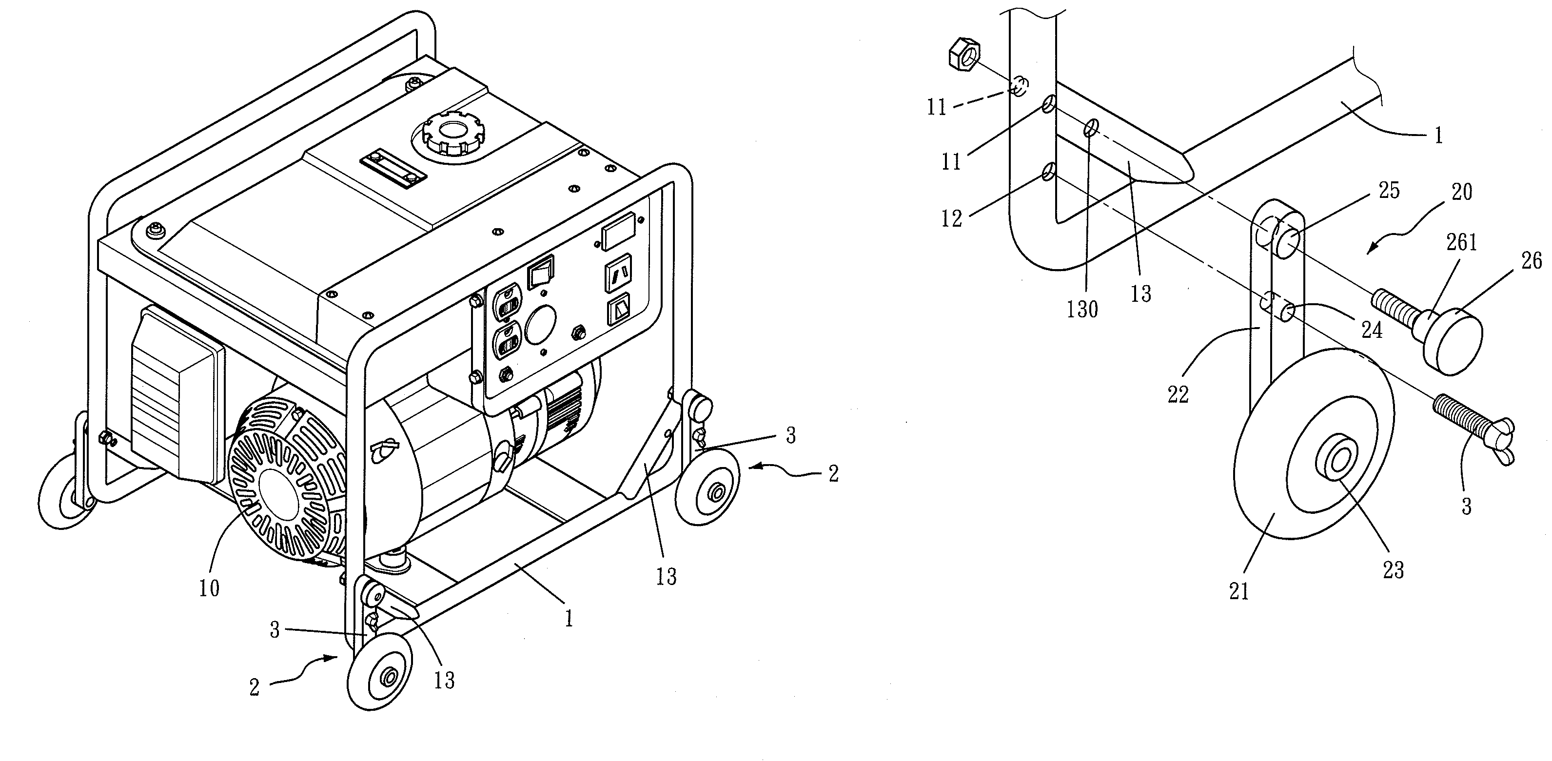
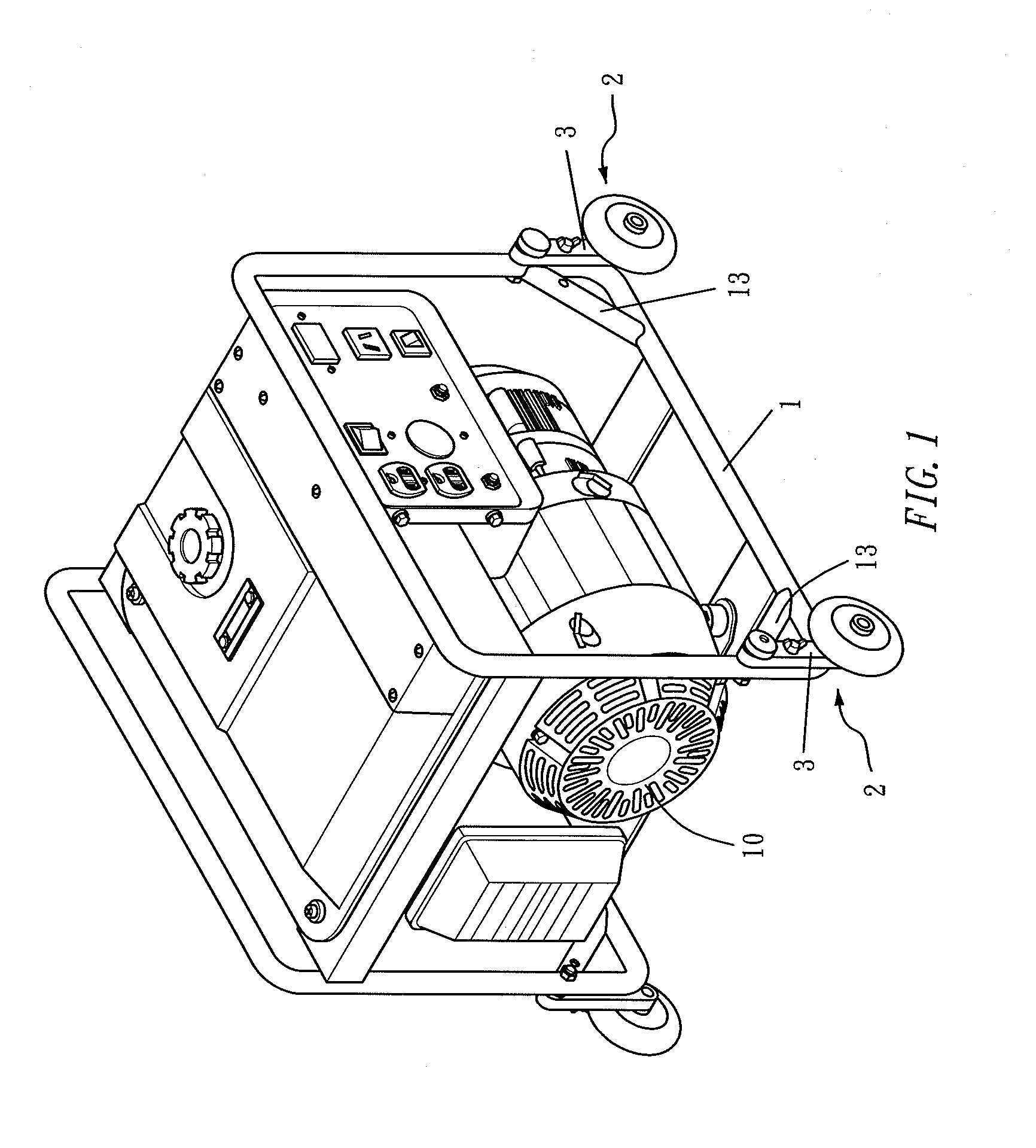
[0022]Referring to FIGS. 1 & 2, a generator 10 (or pump) is lodged in a C-shaped frame 1, and roller apparatus 2 is set up at the bottom of the frame 1, which comprises plural (can be four) rollers 21 (wheels) rolling along the ground, and plural (can be four) link units 20 to join each roller 21 to the frame 1. For easier illustration, one end of the frame 1 and a single link unit 20 is exemplified.

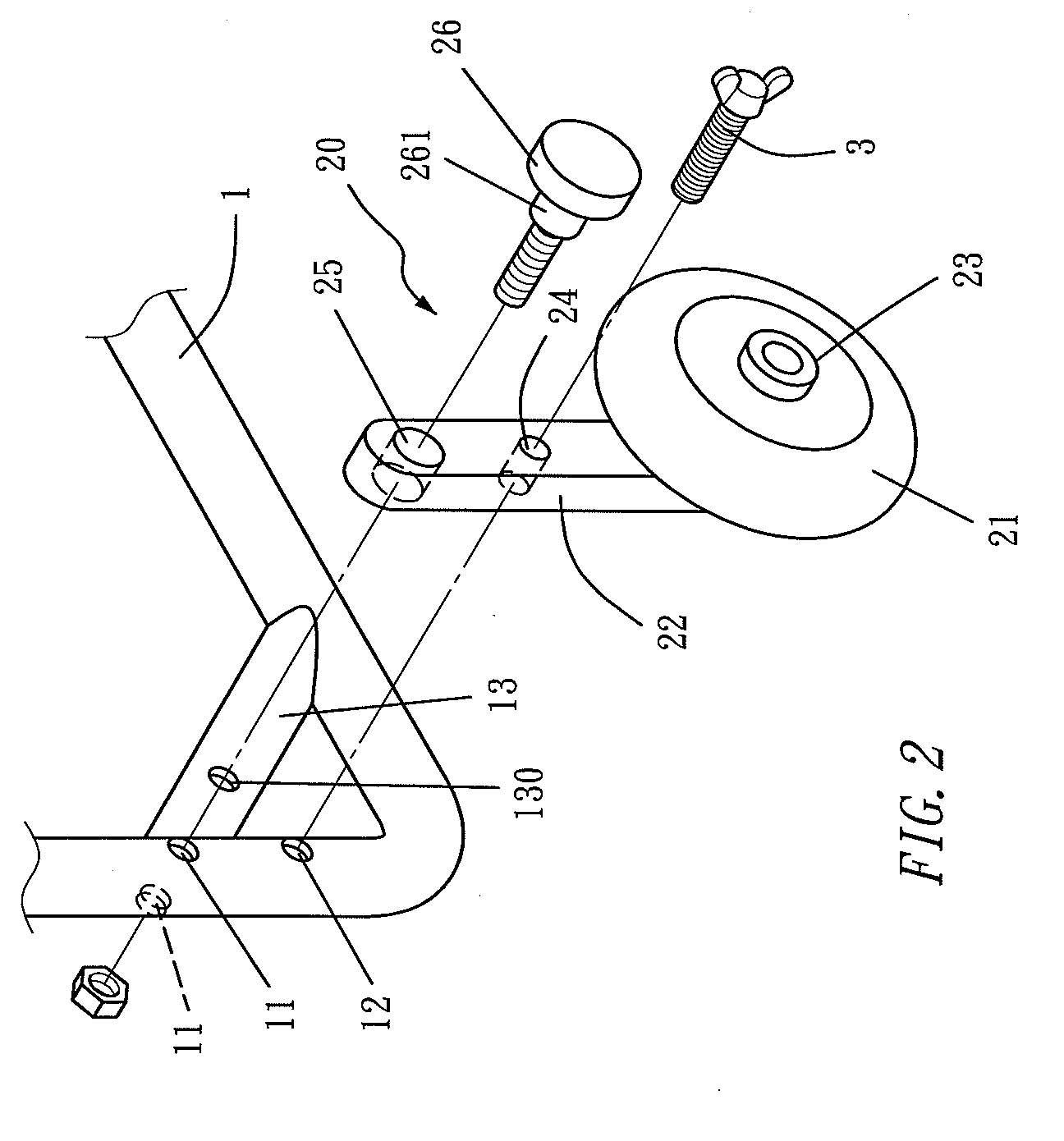
[0023]The frame 1, having a through hole 11 and a screw hole 12 at the top and bottom of its bottom portion, is provided with a oblique brace 13 at each bottom corner, where the brace 13 has its both ends join fixedly to the frame 1 and a screw hole 130 in its middle.

[0024]The link unit 20, aside from the aforesaid brace 13, comprises: a wheel carr...


PUM


Abstract

A roller apparatus for generator, pump and the like is disclosed, where the generator, pump or the like is lodged in a frame, and the roller apparatus is set up at the bottom of the frame, comprising: a plurality of rollers, for rolling along the ground; and a plurality of link units, for linking each roller to the frame, where each link unit is provided with: a brace, obliquely set up at each bottom corner of the frame with a screw hole; a wheel carrier, having its bottom portion join fixedly to the roller and its top portion fixed by a fastener with a shaft portion, for oscillating up and down, and having a screw hole at its middle; and a fixing article, joining the wheel carrier. Through joining the wheel carrier with the frame together by the fixing article, the rollers is ready to unfold for rolling on the ground, or through joining the wheel carrier with the brace together by the fixing article, the rollers is ready to fold aside from the ground, to achieve simplicity in structure and handiness in manipulation.

Description

BACKGROUND OF THE INVENTION[0001]1. Field of the Invention[0002]This invention relates generally to roller apparatus for generator, pump and the like and more particularly to one that is simple in structure and easy in handling the folding and unfolding.[0003]2. Description of the Prior Art[0004]Prior art generators and pumps are mostly immobile types. Due to the vast volume and hefty weight, it is time consuming to move generators and pumps. And wheels are always added to form a mobile type of generator (or pump). As shown in FIG. 6, a generator 4 is lodged in a frame 40, where the frame 40 is provided with a wheel 41 at the bottom of each corner, which is available to roll along the ground. The wheel 41 is axially connected to the bottom of a lifting shaft 42, and the lifting shaft 42 wears a spring 43 and both together are placed in a sleeve 44, where the sleeve 44 is fixedly joined to the frame 40 and is penetrated by a bolt 45 which props against a locating slot 46 or a plane 4...

Claims


Application Information

Patent Timeline
IPC IPC(8): B62B3/00
CPCB62B3/02B62B2205/12B62B5/049
Inventor WANG, WEN CHANG
Owner WANG WEN CHANG
Why Eureka
Try Eureka