
LED bulb with an enlarged irradiation range by arranging led elements in three-dimension

Inactive Publication Date: 2011-01-13
STEKELENBURG ALBERT
View PDF4 Cites 6 Cited by
  • Summary
  • Abstract
  • Description
  • Claims
  • Application Information

AI Technical Summary

Benefits of technology

[0008]In one aspect of the invention the LED elements are arranged and shaped as an upwardly tapered to

Problems solved by technology

However, the well known LED lamp suffers from a disadvantage.
As a result, side light is relatively weak.

Method used


Image

  • LED bulb with an enlarged irradiation range by arranging led elements in three-dimension
  • LED bulb with an enlarged irradiation range by arranging led elements in three-dimension
  • LED bulb with an enlarged irradiation range by arranging led elements in three-dimension

Examples


Embodiment Construction

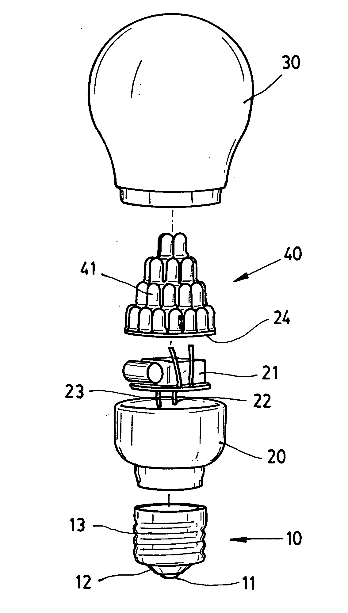
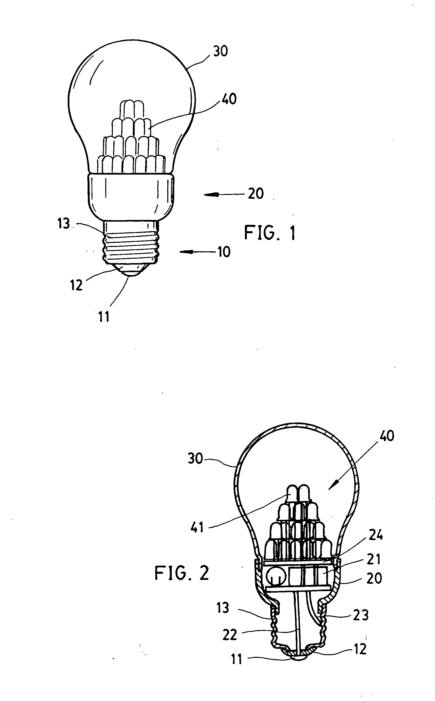
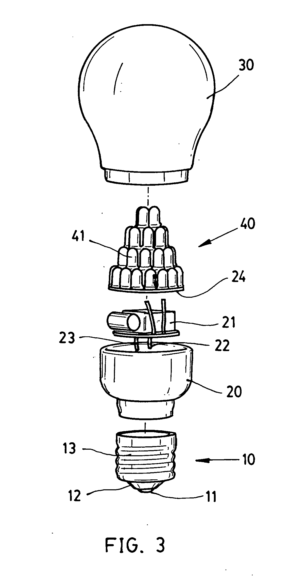
[0013]Referring to FIGS. 1 to 3, an LED bulb in accordance with a preferred embodiment of the invention comprises a base 10, a housing 20, a bulb 30, and an LED assembly 40. Each component is discussed in detail below.

[0014]The base 10 is a well known device and is adapted to mount in an electrical socket. The base 10 comprises a bottom contact 11 as, for example, positive terminal, a metallic element 13 formed of copper, the metallic element 13 being used as, for example, negative terminal, and an insulator 12 formed between the contact 11 and the metallic element 13 for preventing them from electrically contacting each other.

[0015]The hollow housing 20 is adapted to mount on the base 10. Within the housing 20 there are provided an electrical circuit assembly 21 including well known elements such as a capacitor, a resistor, and diodes; two spaced conductors 22, 23 in which the conductor 22 interconnects the electrical circuit assembly 21 and the contact 11 and the conductor 23 inte...


PUM


Abstract

An LED light source includes a housing having a base adapted to mount in an electrical socket; a circuit board received in the housing; an electrical circuit assembly received in the housing, the electrical circuit assembly being electrically connected to both the circuit board and the base; an LED assembly mounted on the circuit board, the LED assembly including a plurality of LED elements electrically connected to the circuit board; and a bulb mounted on an open end of the housing for enclosing the circuit board, the electrical circuit assembly, and the LED assembly, wherein the LED elements are arranged in three-dimension so as to irradiate an enlarged range. The LED elements may be arranged and shaped as a tapered tower, a tree, or a semi-sphere.

Description

BACKGROUND OF THE INVENTION[0001]1. Field of Invention[0002]The invention relates to light sources and more particularly to an LED (light-emitting diode) bulb with an enlarged irradiation range by arranging its LED elements in three-dimension.[0003]2. Description of Related Art[0004]LED lamps have advantages including longer life, less power consumption (i.e., more energy-efficient), and no special ballasts being required. Thus, LED based light sources have gradually replace conventional incandescent lamps and fluorescent lamps as the dominant light sources in our daily life.[0005]Also, LED lamps employing a plurality of LEDs are commercially available. However, the well known LED lamp suffers from a disadvantage. In detail, these LEDs are arranged in two-dimension, i.e., on a plate. Thus, light only directs toward one side of the plate. As a result, side light is relatively weak. Thus, a need for improvement exists.[0006]Also, there have been numerous suggestions in prior patents f...

Claims


Application Information

Patent Timeline
IPC IPC(8): H01J13/46F21S4/00
CPCF21K9/135F21Y2111/001F21Y2101/02F21V3/00F21K9/232F21Y2115/10F21Y2107/00
Inventor STEKELENBURG, ALBERT
Owner STEKELENBURG ALBERT
Learn More