Magnetic Head Slider Locking Apparatus

a technology of slider and locking device, which is applied in the direction of magnetic recording, instruments, data recording, etc., can solve the problems of increasing cost, affecting durability, and affecting the durability of the device, so as to achieve the effect of preventing the spring portion from touching, and not increasing the size of the spring portion

Active Publication Date: 2011-01-13
SANCALL
View PDF8 Cites 7 Cited by
  • Summary
  • Abstract
  • Description
  • Claims
  • Application Information

AI Technical Summary

Benefits of technology

[0038]The configuration makes it possible to effectively prevent contact of the spring portion to the fixed

Problems solved by technology

However, upon conducting the performance tests in the state where the magnetic head slider is fixed to the head mount region, if the results of the tests on the magnetic head slider are defective, it is necessary to discard not only the magnetic head slider but also the magnetic head suspension to which the magnetic head slider has been fixed, resulting in increase in cos

Method used


Image

  • Magnetic Head Slider Locking Apparatus
  • Magnetic Head Slider Locking Apparatus
  • Magnetic Head Slider Locking Apparatus

Examples


Embodiment Construction

[0047]Hereinafter, one preferred embodiment of a magnetic head slider locking apparatus according to the present invention will be described, with reference to the attached drawings.

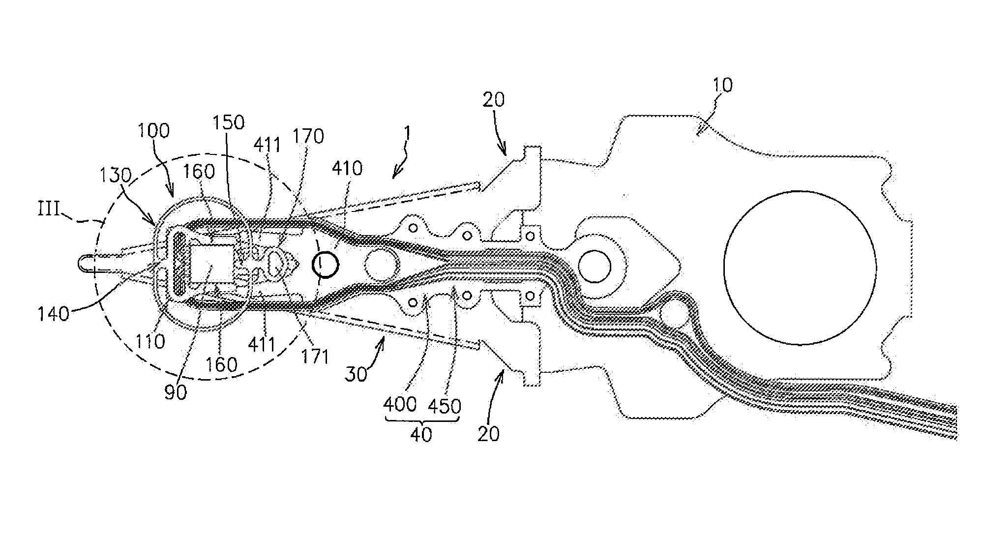
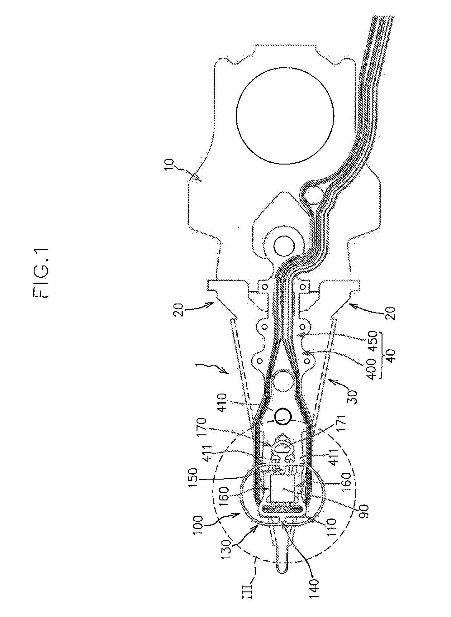
[0048]FIG. 1 is a bottom view (a bottom plan view as viewed from a side close to a disk surface) of a magnetic head suspension 1 to which a magnetic head slider locking apparatus 100 according to the present embodiment is mounted. FIG. 1 indicates welding points with using small circles.

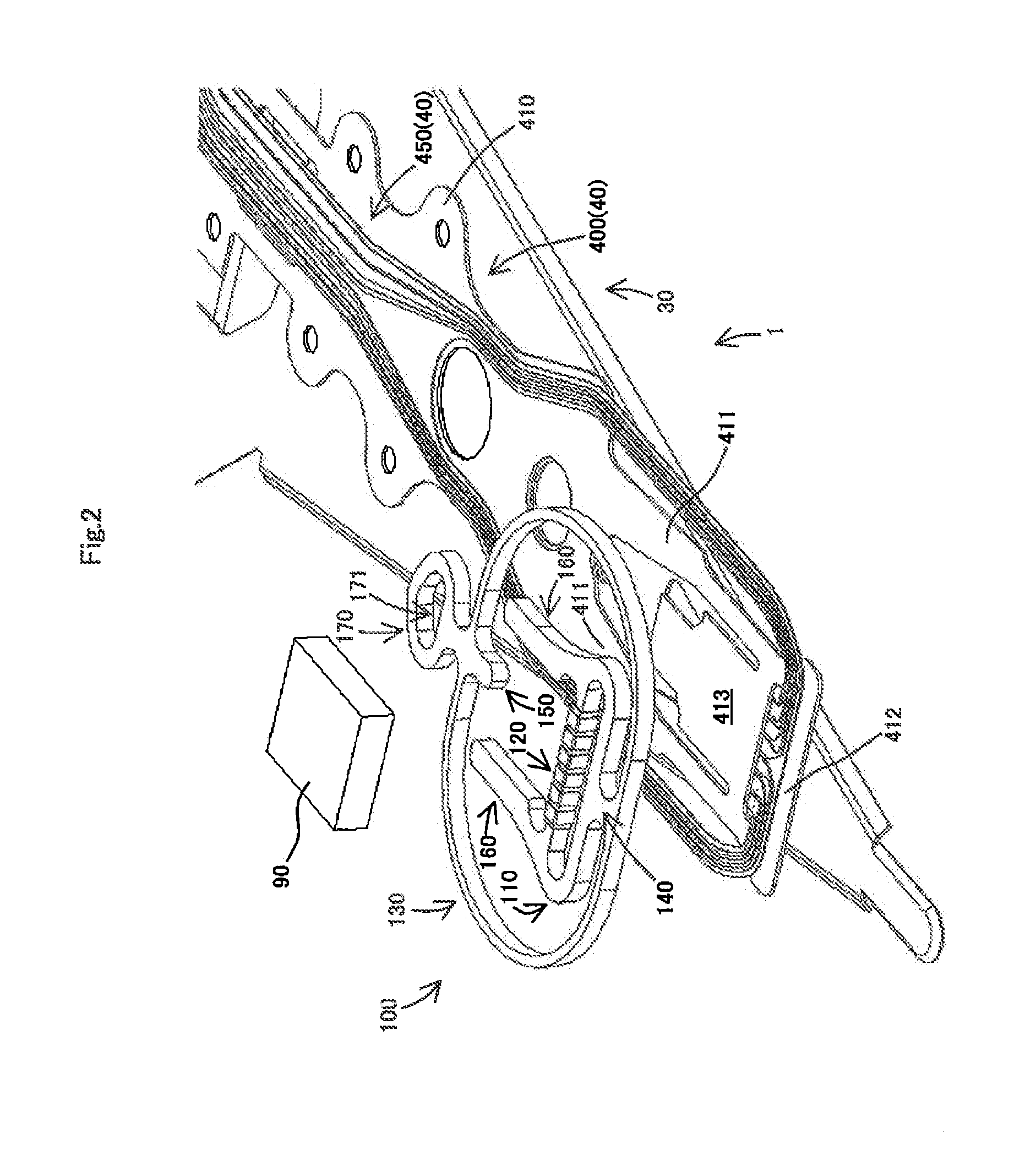
[0049]FIG. 2 is an exploded perspective view of a magnetic head slider 90, the magnetic head slider locking apparatus 100 and the magnetic head suspension 1.

[0050]The magnetic head slider locking apparatus 100 is a member for detachably mounting the magnetic head slider 90 to the magnetic head suspension 1.

[0051]More specifically, the magnetic head slider locking apparatus 100 is capable of causing the magnetic head slider 90 to be retained at the magnetic head suspension 1 so as to allow performance tests of the magnetic...


PUM


Abstract

The present invention aims to realize cost reduction and improved durability of a magnetic head slider locking apparatus for detachably mounting a magnetic head slider to a magnetic head suspension.
The magnetic head slider locking apparatus includes a fixed portion having a distal-side engage portion with which a distal end of the slider is engaged and being fixed to a flexure part, an endless spring portion surrounding the fixed portion in a plan view, a connection portion connecting the fixed portion to the spring portion, and a proximal-side engage portion provided to the spring portion so as to be engaged with a proximal end of the slider. The spring portion takes an initial posture where no external operational force is applied thereto so that the proximal-side engage portion is located closer to a distal end side in the suspension longitudinal direction than the proximal end of the slider, and also takes an elastically deformed posture where an external operational force is applied thereto so that the proximal-side engage portion is located closer to a proximal end side in the suspension longitudinal direction than the proximal end of the slider.

Description

BACKGROUND OF THE INVENTION[0001]1. Field of the Invention[0002]The present invention relates to a magnetic head slider locking apparatus for detachably mounting a magnetic head slider, which reads and / or writes data from and to a recording medium such as a hard disk drive, to a magnetic head suspension.[0003]2. Related Art[0004]It is preferable to conduct performance tests on reading properties and / or writing properties as well as levitation properties of a magnetic head slider for reading and / or writing data in accordance with a state of use of the magnetic head slider, that is, in a state where the magnetic head slider is mounted to a magnetic head suspension having a configuration identical with that of a magnetic head suspension to be mounted thereto.[0005]More specifically, an ordinary magnetic head suspension includes a supporting part that is connected directly or indirectly to an actuator such as a voice coil motor, a load bending part that is connected to the supporting pa...

Claims


Application Information

Patent Timeline
IPC IPC(8): G11B21/16
CPCG11B5/4826
Inventor WAKAHARA, MASAHITO
Owner SANCALL
Why Eureka
Try Eureka