Magnetic Head Slider Locking Apparatus

Active Publication Date: 2011-08-25
SANCALL
View PDF6 Cites 9 Cited by
  • Summary
  • Abstract
  • Description
  • Claims
  • Application Information

AI Technical Summary

Benefits of technology

The configuration makes it possible to effectively prevent contact of the spring portion to the fixed po

Problems solved by technology

However, upon conducting the performance tests in the state where the magnetic head slider is fixed to the head mount region, if the results of the tests on the magnetic head slider are defective, it is necessary to discard not only the magnetic head slider but also the magnetic head suspension to which the magnetic head slider has been fixed, resulting in increase in cost.
On the other hand, this slider support device has the foll

Method used


Image

  • Magnetic Head Slider Locking Apparatus
  • Magnetic Head Slider Locking Apparatus
  • Magnetic Head Slider Locking Apparatus

Examples


first embodiment

Hereinafter, one preferred embodiment of a magnetic head slider locking apparatus according to the present invention will be described, with reference to the attached drawings.

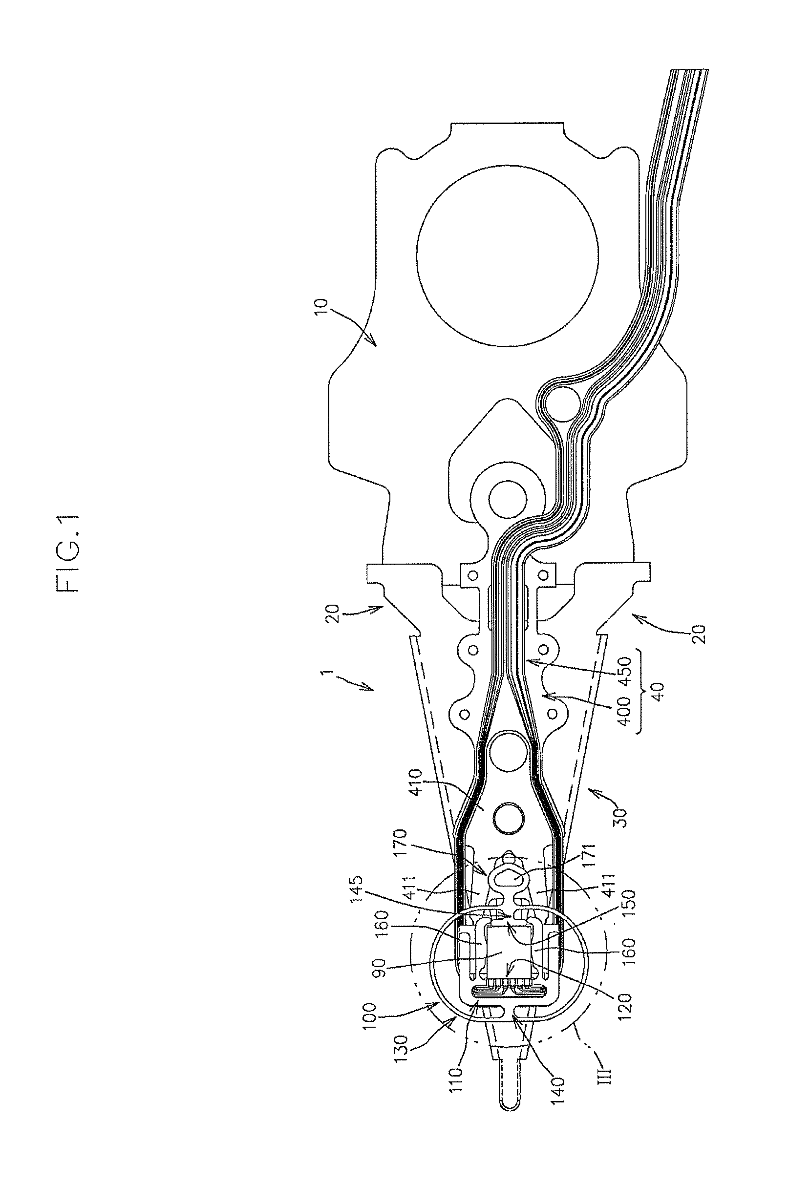
FIG. 1 is a bottom view (a bottom plan view as viewed from a side close to a disk surface) of a magnetic head suspension 1 to which a magnetic head slider locking apparatus 100 according to the present embodiment is mounted. FIG. 1 indicates welding points with using small circles.

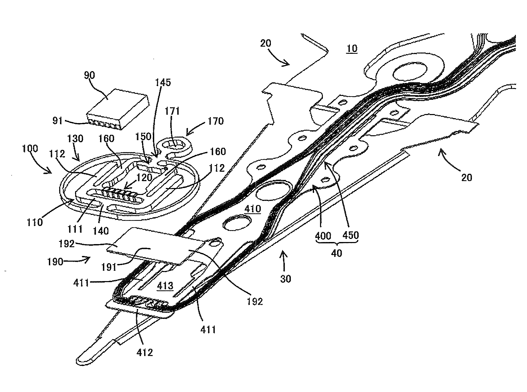
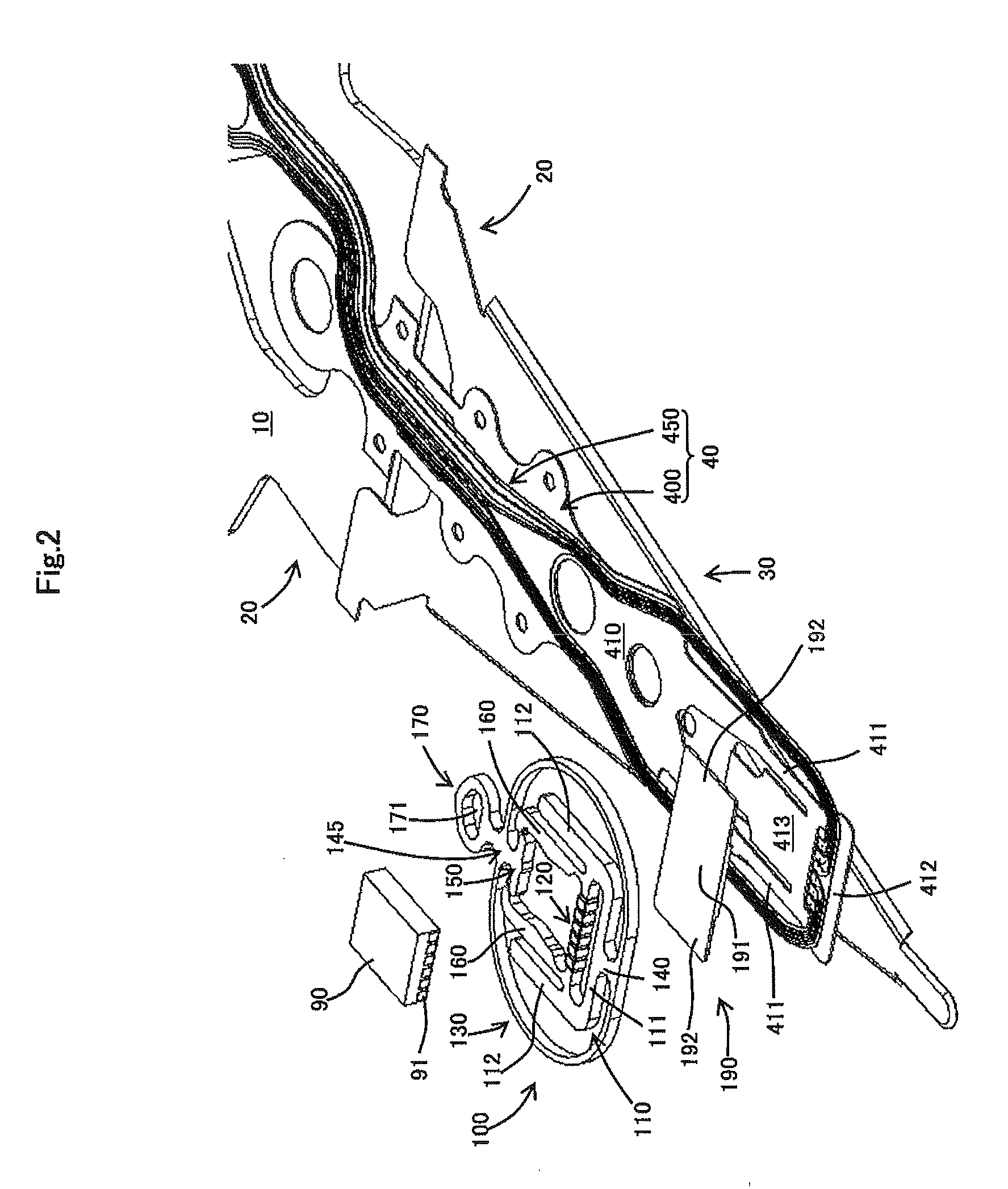
FIG. 2 is an exploded perspective view of a magnetic head slider 90, the magnetic head slider locking apparatus 100 and the magnetic head suspension 1, as viewed from the side close to the disk surface.

The magnetic head slider locking apparatus 100 is a member for detachably mounting the magnetic head slider 90 to the magnetic head suspension 1.

More specifically, the magnetic head slider locking apparatus 100 is capable of causing the magnetic head slider 90 to be retained at the magnetic head suspension 1 so as to allow performance ...

second embodiment

Hereinafter, another embodiment of the magnetic head slider locking apparatus according, to the present invention will be described, with reference to the attached drawings.

FIG. 10 is a perspective view of a magnetic head slider locking apparatus 100B according to the present embodiment.

In the drawing, identical parts to those of the first embodiment have been given the same reference numerals to omit a detailed description thereof.

The magnetic head slider looking apparatus 100 according to the first embodiment is configured to sandwich the magnetic head slider 90 in the suspension longitudinal direction and also sandwich the magnetic head slider 90 in the suspension width direction by the-paired right and left arm portions 160 capable of being elastically deformed in the suspension width direction.

The magnetic head slider locking apparatus 100B is same as the first embodiment with respect to a configuration for sandwiching the magnetic head slider 90 in the suspension longitudinal ...


PUM


Abstract

In the magnetic head slider locking apparatus according to the present invention, a spring portion takes a sandwiching posture in which a center region of a proximal-side engage portion sandwiches a magnetic head slider in a suspension longitudinal direction in cooperation with a distal-side engage portion when an operational force to the spring portion is released after the magnetic head slider has been mounted in a state where the spring portion has been elastically deformed from an initial posture to an elastically deformed posture. Paired arm are elastically deformed by paired side regions of the proximal-side engage portion that are moved upon posture change of the spring portion from the initial posture to the elastically deformed posture so as to take a distant posture in which a distance between the paired arm portions is wider than the width of the magnetic head slider, and are shifted to take a sandwiching posture of sandwiching the magnetic head slider from both sides in the suspension width direction upon posture change of the spring portion from the elastically deformed posture to the sandwiching posture.

Description

BACKGROUND OF THE INVENTION1. Field of the InventionThe present invention relates to a magnetic head slider locking apparatus for detachably mounting a magnetic head slider, which reads and / or writes data from and to a recording medium such as a hard disk drive, to a magnetic head suspension.2. Related ArtIt is preferable to conduct performance tests on reading properties and / or writing properties as well as levitation properties of a magnetic head slider for reading and / or writing data in accordance with a state of use of the magnetic head slider, that is, in a state where the magnetic head slider is mounted to a magnetic head suspension having a configuration identical with that of a magnetic head suspension to be mounted thereto.More specifically, an ordinary magnetic head suspension includes a supporting part that is connected directly or indirectly to an actuator such as a voice coil motor, a load bending part that is connected to the supporting part and generates a load to pre...

Claims


Application Information

Patent Timeline
IPC IPC(8): G11B5/54
CPCG11B5/4826
Inventor WAKAHARA, MASAHITO
Owner SANCALL
Why Eureka
Try Eureka