Threaded joint with improved resilient seal ring
a resilient seal ring and threaded joint technology, applied in the direction of washers, rod connections, ropes and cables for vehicles/pulleys, etc., can solve the problems of deformation of the seal, and damage to the seal ring during mounting and/or make-up, so as to improve the sealing capacity of the ring and consequently of the joint, and enhance the contact of the first seal ring
- Summary
- Abstract
- Description
- Claims
- Application Information
AI Technical Summary
Benefits of technology
Problems solved by technology
Method used
Image

Examples
first embodiment
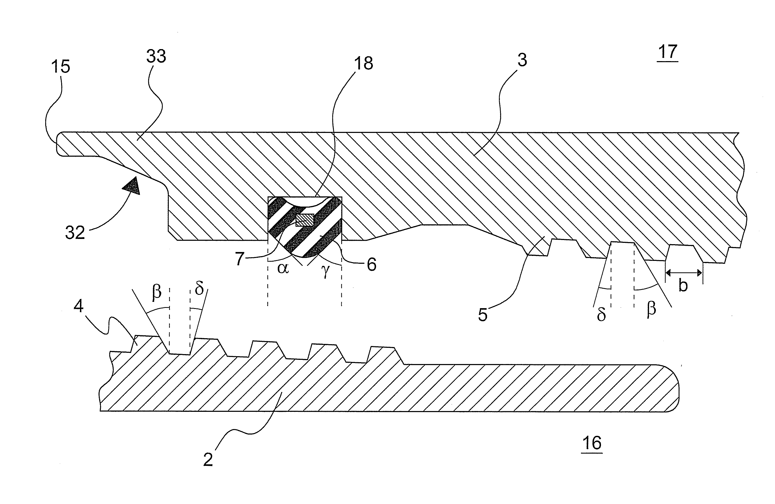
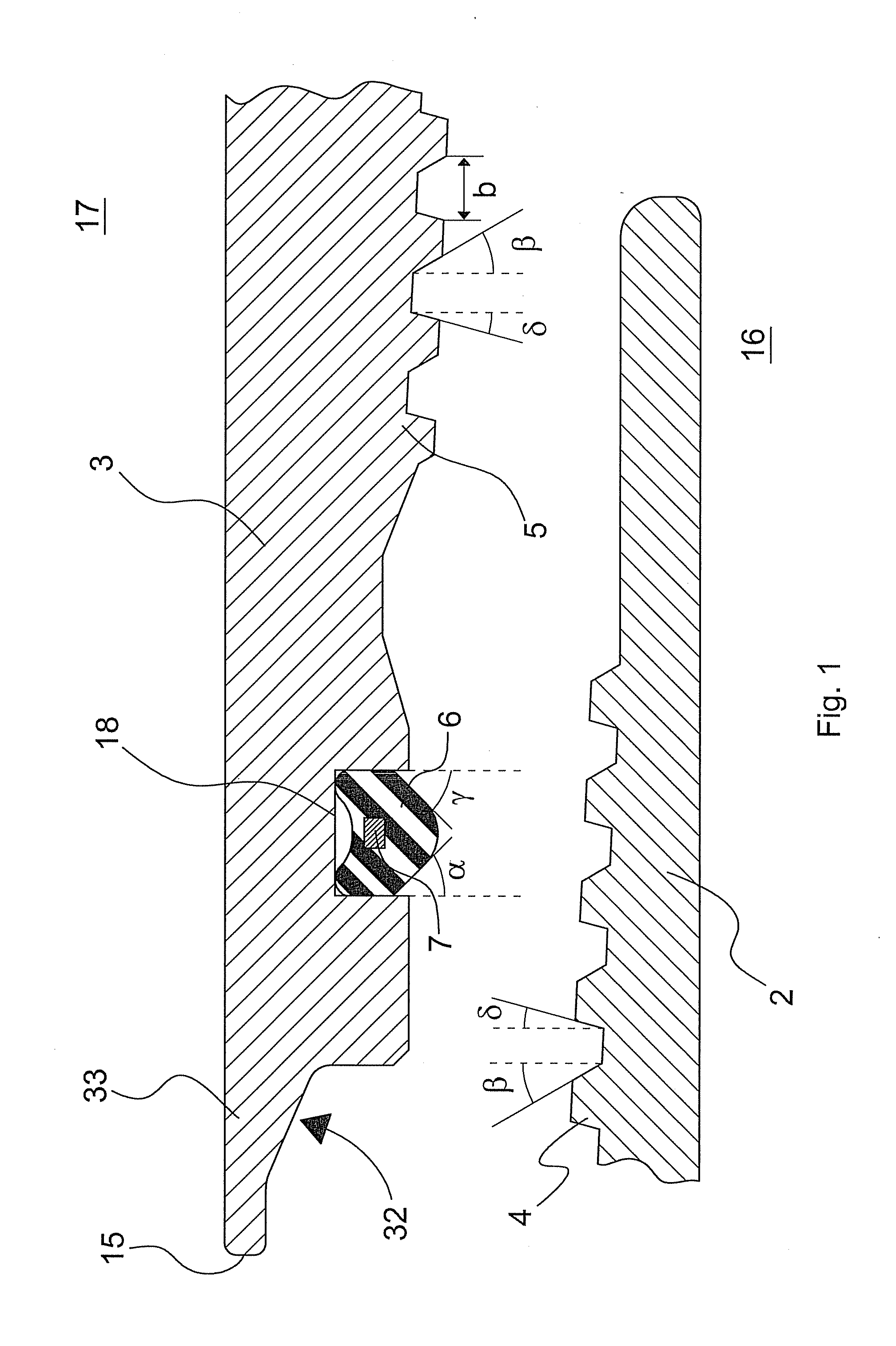
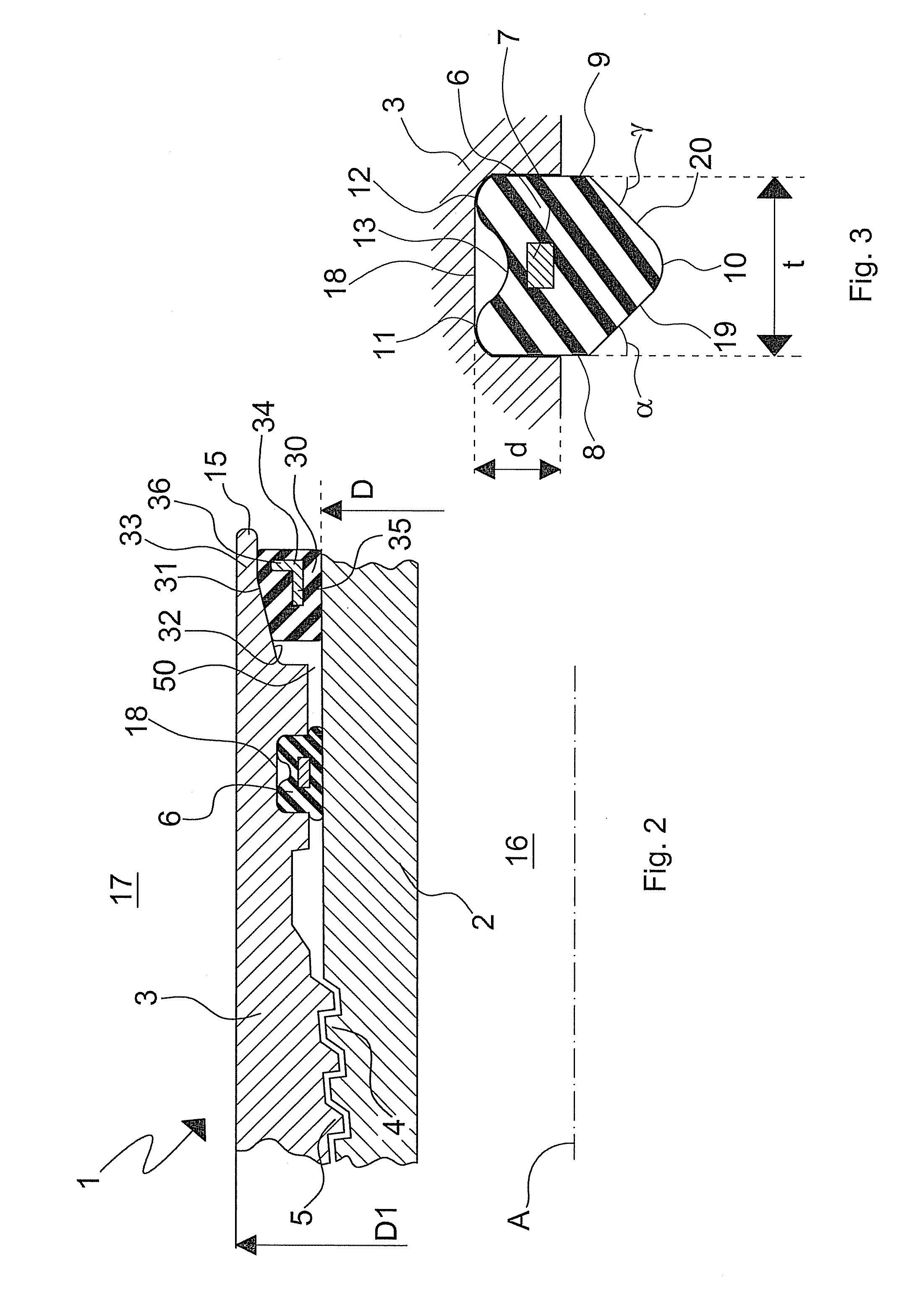
[0045]With particular reference to the FIGS. 1 to 3, there is shown a threaded joint, indicated overall by reference numeral 1, connecting two pipes together: a male pipe, commonly called pin 2, with a nominal external diameter D, and a female pipe also called box 3, with a nominal external diameter D1 equal to or greater than D.
[0046]The pin 2 has an external threaded portion 4 with male threads of appropriate profile, e.g. trapezoidal, the box 3 having an internal threaded portion 5 with female threads of profile complementary to that of the male threads.
[0047]The common axis of pin 2 and box 3 is indicated by A. The box 3 ends with a nose 15. The joint defines an inner space 16, containing the axis A of pin and box, in which the fluid, for example a hydrocarbon, such as natural gas or petroleum or other similar fluid, flows and an outer space 17 which can be in contact with fluids of various kinds such as sea water in some applications.
[0048]At the extremity of the box 3 there is...
second embodiment
[0051]FIG. 6 shows the first seal ring 40 having a U-shaped cross section, with the external arm 41 preferably shorter than the internal arm 42. The reinforcement ring 43, embedded in the body of the seal ring 40, has an L-shaped cross section, viewed in projection on an axial plane, with two arms 44, 45 perpendicular to each other. The angle ψ of the L-shape can also be slightly larger or smaller than 90° and the two arms 44, 45 can be of different length. The arm 44 is embedded in the external arm 41 of the body of the seal ring 40 parallel to the joint axis A, whereas the arm 45 is embedded in the body of the seal ring 40 perpendicularly to the joint axis A.
[0052]The reinforcement ring in both embodiments of the first seal ring can be completely embedded in the seal ring or can have one of its surfaces exposed to the exterior of the seal ring, either flush to a base or protruding from this base.
[0053]Advantageously the internal surface 37, 47 of the first seal ring 30, 40 has a f...
third embodiment
[0076]With particular reference to FIG. 8, where the same features of the embodiments described above are indicated by the same reference numerals, there is shown the joint according to the invention.
[0077]At the extremity of the box 3 there is located the first seal ring 60 of elastomeric material. This seal ring 60 has a cross section on an axial plane substantially rectangular and provided with a small rib 61 in correspondence with an edge of said cross section. The small rib 61 (FIG. 9) is the section of an annular protuberance protruding in the axial direction.
[0078]The seal ring 60 can also be provided with a reinforcing ring, for example having a cross section of L-shape, completely embedded in the seal ring or having one of its surfaces exposed to the exterior of the seal ring, either flush to a base or protruding from this base.
[0079]The internal surface of the nose 15 of the box 3 has a cylindrical shape complementary to the shape of the external surface of the seal ring 6...
PUM
 Abstract
Description
Claims
Application Information
 - R&D Engineer
- R&D Manager
- IP Professional
- Industry Leading Data Capabilities
- Powerful AI technology
- Patent DNA Extraction
Browse by: Latest US Patents, China's latest patents, Technical Efficacy Thesaurus, Application Domain, Technology Topic.
© 2024 PatSnap. All rights reserved.Legal|Privacy policy|Modern Slavery Act Transparency Statement|Sitemap