
Stacked electrical connector with a new type of spacer

Inactive Publication Date: 2011-01-13
HON HAI PRECISION IND CO LTD
View PDF1 Cites 1 Cited by
  • Summary
  • Abstract
  • Description
  • Claims
  • Application Information

AI Technical Summary

Benefits of technology

[0007]To fulfill the above-mentioned object, an electrical connector comprises a row of terminals arranged in the first direction and comprising contact portions and soldering tails, an insulative housing in which the contact portions of the terminal are arranged and behind which the soldering tails are arranged and a spacer securely attached to the insulative housing to position the soldering tail. The spacer has a top face and a bottom face and a row of through holes running through the top face and the bottom face to receive the corresponding soldering tails thereof Each of through holes includes a guiding hole communicating with the top face and a receiving hole communicating with the bottom face. The guiding hole defines guiding faces intersecting with the top face to form a frame intersection. The frame intersections of the row of through holes are aligned in the first direction while the receiving holes of the row of the through holes are offset in the first direction.

Problems solved by technology

But during assembly process, the tail portions might be damaged by the spacer, because the tail portions can not be lead correctly by the positioning holes.

Method used


Image

  • Stacked electrical connector with a new type of spacer
  • Stacked electrical connector with a new type of spacer
  • Stacked electrical connector with a new type of spacer

Examples


Embodiment Construction

[0016]Reference will now be made in detail to the preferred embodiment of the present invention.

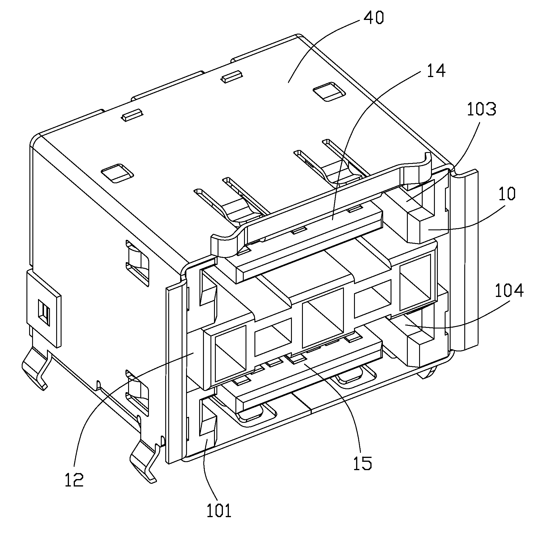
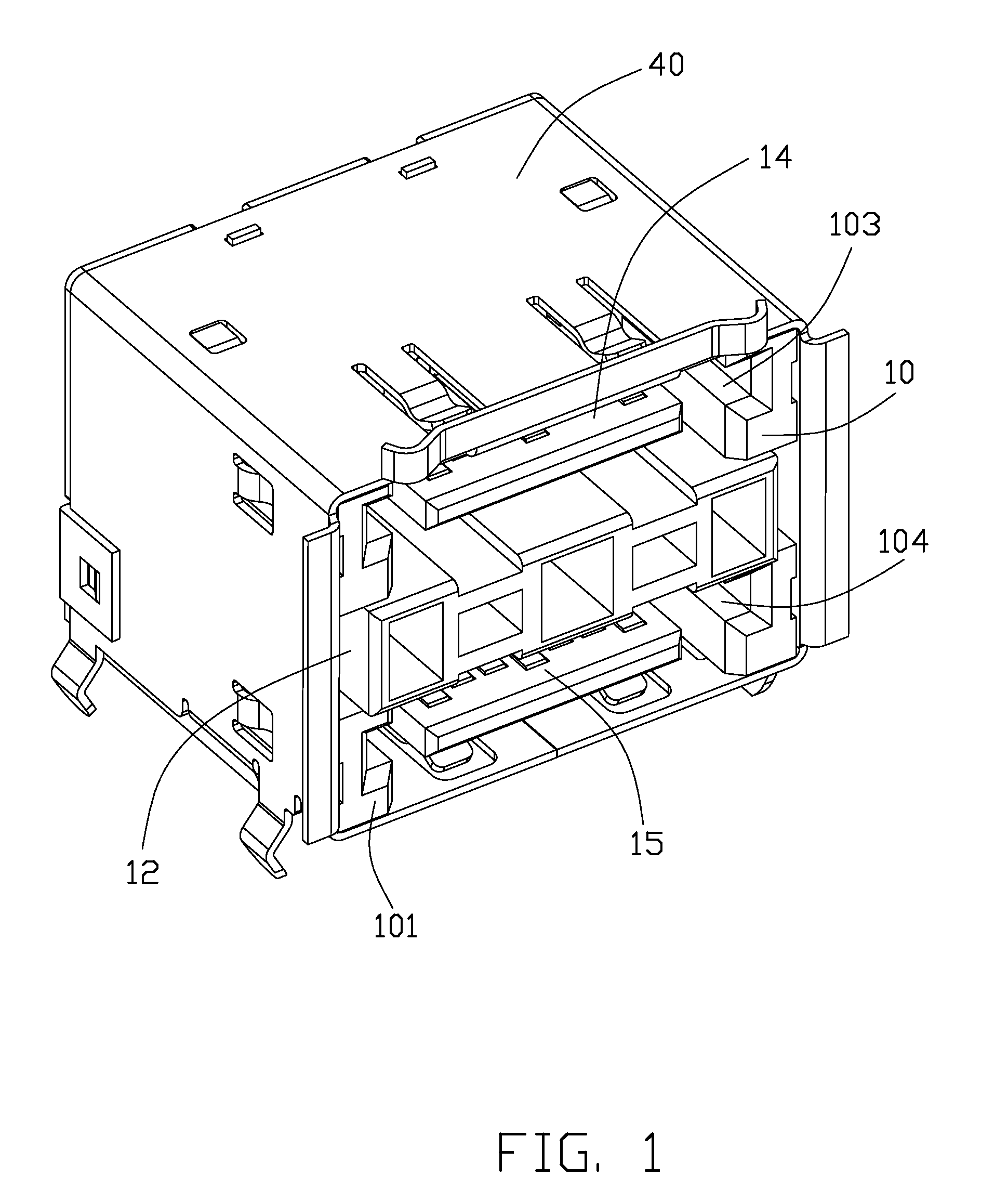
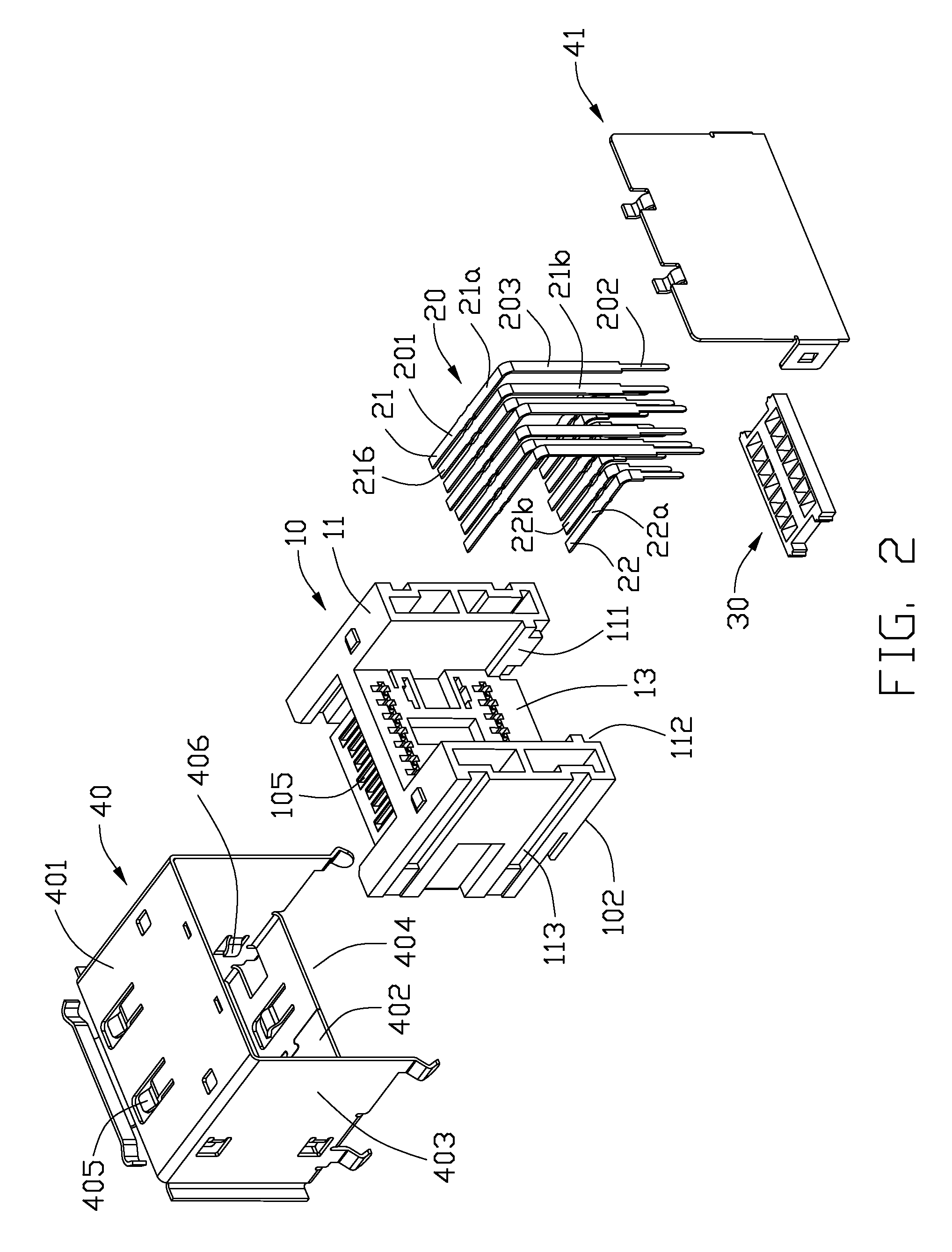
[0017]With reference to FIGS. 1-4, a multiple-port electrical connector 1 in accordance with the present invention, which is mountable on a printed circuit board (not shown), comprises an insulative housing 10, a plurality of terminals 20 disposed in the housing 10, a positioning spacer 30 attached onto the housing 10, and a metal shell 40 secured to the housing 10.

[0018]Referring to FIG. 2 combination with FIG. 1, The insulative housing 10 comprises a pair of side walls 11 extending parallel to each other, a partition wall 12 extending horizontally between the two side walls 11, and a middle wall 13 extending perpendicularly to the partition wall 12 and connecting the two side walls 11. A first cavity 103 and a second cavity 104 are respectively defined by the side walls 11 and the partition wall 12 for receiving corresponding mating complementary connectors (not shown) therein. The insu...


PUM


Abstract

An electrical connector includes a row of terminals arranged in the first direction and including contact portions and soldering tails, an insulative housing in which the contact portions of the terminal are arranged and behind which the soldering tails are arranged and a spacer securely attached to the housing to position the soldering tail. The spacer has a top face and a bottom face and a row of through holes running through the top face and the bottom face to receive the corresponding soldering tails thereof Each of through holes includes a guiding hole communicating with the top face and a receiving hole communicating with the bottom face. The guiding hole defines guiding faces intersecting with the top face to form a frame intersection. The frame intersections are aligned in the first direction while the receiving holes are offset.

Description

BACKGROUND OF THE INVENTION[0001]1. Field of the Invention[0002]The present invention generally relates to an electrical connector, and particularly to an electrical connector mounted on a printed circuit board.[0003]2. Description of the Prior Art[0004]Serial Advanced Technology Attachment (Serial ATA) connectors provide a storage interface for ATAPI (Advanced Technology Attachment Packet Interface) devices and hard disk drives, which are main storage peripheral devices of computer systems. Conventionally, a Serial ATA connector comprises an insulating housing, a plurality of terminals received in the housing and a spacer employed to be assembled onto the insulative housing with a plurality of positioned holes defined thereon. A plurality of tail portions of the terminals located in two arrays are inserted into the positioning holes. Such Serial ATA connectors can be found in TW Patent No. M314956 issued to WU LIANG-CAI on Nov. 10, 2006. The tail portions are located in a staggered...

Claims


Application Information

Patent Timeline
IPC IPC(8): H01R27/00H01R24/00
CPCH01R12/712
Inventor LUO, HONG-JINGWANG, XIN-YU
Owner HON HAI PRECISION IND CO LTD
Learn More