Eureka AIR delivers breakthrough ideas for toughest innovation challenges, trusted by R&D personnel around the world.

Appliance requiring intake air during operation

Active Publication Date: 2011-01-13
CRANE USA INC
View PDF3 Cites 0 Cited by
  • Summary
  • Abstract
  • Description
  • Claims
  • Application Information

AI Technical Summary

Benefits of technology

[0027]In one form the spacing wall has an area that is substantially less than the area of the downwardly facing surface on t

Problems solved by technology

This design permits potentially high volume air handling.
Depending upon the nature of the carpet, the supporting appliance feet may depress into the carpet, thereby reducing the clearance from that for which the appliance is optimally designed.
In a worse case, the intake may be substantially or fully blocked, in which event the appliance may be nonfunctional.
Even though the placement of the appliance may account for inefficient operation, or a total failure to operate, the consumer may blame the appliance manufacturer for these problems.
This reaction may have a devastating effect upon sales, particularly in an age when consumer feedback through surveys is actively solicited and such feedback is widely disseminated in hard copy form and electronically over the internet.

Method used


Image

  • Appliance requiring intake air during operation
  • Appliance requiring intake air during operation
  • Appliance requiring intake air during operation

Examples


Embodiment Construction

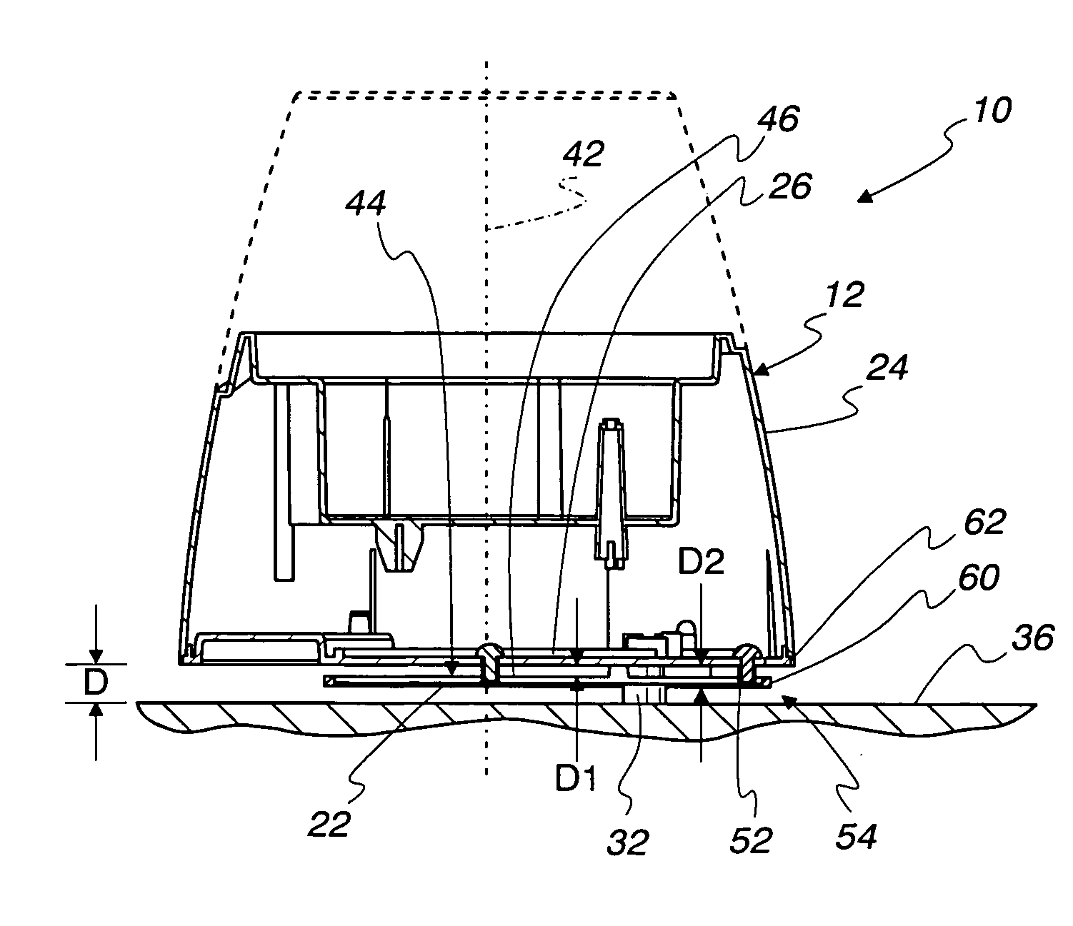
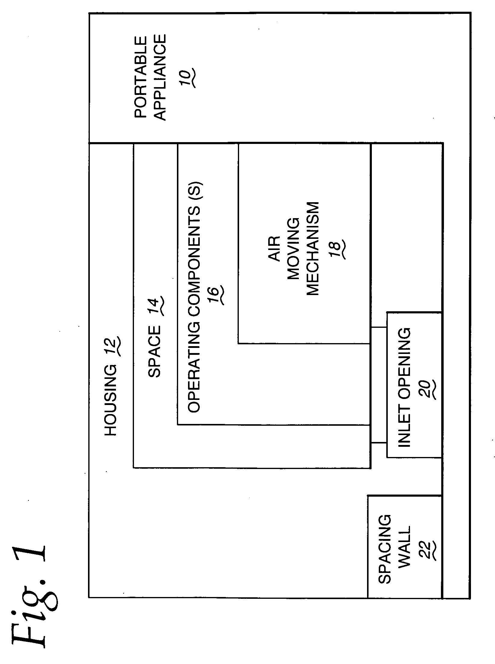
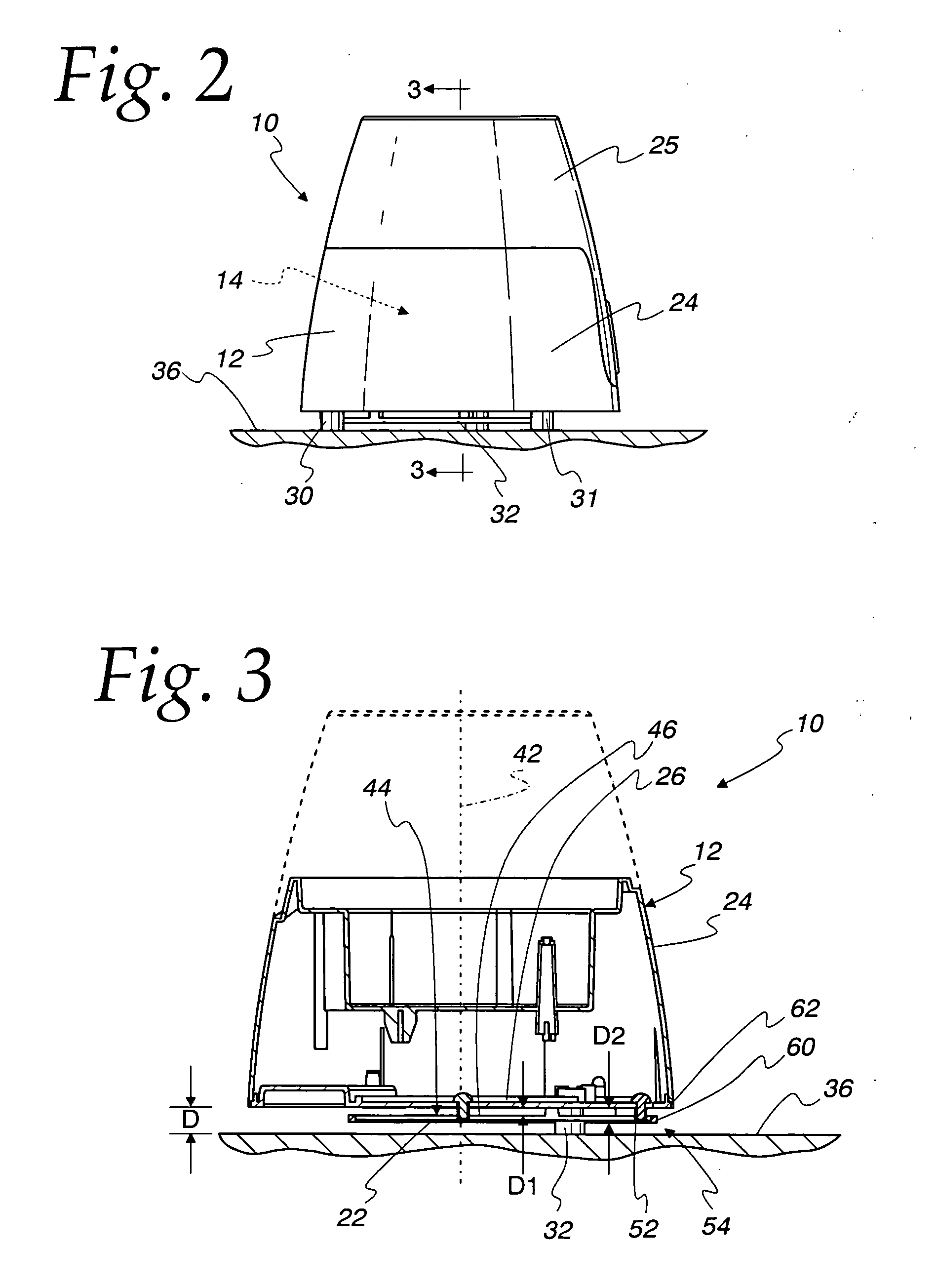
[0039]In FIG. 1, a portable appliance, according to the present invention, is shown at 10. The portable appliance 10 is shown schematically in FIG. 1 to encompass virtually an unlimited number of different constructions that perform potentially different functions, such as introducing humidified or purified air into a surrounding space. Generally, the portable appliance 10 is one having a housing 12 defining a space 14 for at least one operating component 16. One or more of the operating components 16 define an air moving mechanism 18 for causing atmospheric air to be drawn into the housing space 14 through an inlet opening 20 to at least one of: a) cool at least one of the operating components 16; b) be treated by at least one of the operating components 16; and c) cause movement of a fluid within the housing space 14. The housing 12 further has a spacing wall 22 that underlies the inlet opening 20 and bounds an intake space through which atmospheric air is guided in a generally ho...


PUM


Abstract

A portable appliance with a housing defining a space for operating components. The operating components define an air moving mechanism for causing atmospheric air to be drawn into the housing space to at least one of: a) cool at least one of the operating components; b) be treated by at least one of the operating components; and c) cause movement of a fluid within the housing space. The housing has a first wall with a downwardly facing surface in which an inlet opening is defined through which atmospheric air is drawn into the housing space. The housing further has a spacing wall that underlies the inlet opening and bounds in conjunction with the first wall an intake space through which atmospheric air is guided in a generally horizontal path towards the inlet opening.

Description

BACKGROUND OF THE INVENTION[0001]1. Field of the Invention[0002]This invention relates to appliances, such as air treatment appliances and, more particularly, to an appliance requiring a continuous intake of atmospheric air during operation thereof.[0003]2. Background Art[0004]A large number of consumer appliances are designed to continuously intake air during operation thereof. This air may be used for cooling purposes and / or treated by the particular apparatus and thereafter directed to a surrounding space.[0005]An example of the latter appliance is one that purifies air. Air to be treated is drawn into a housing at an intake location, treated by being exposed to filter media and / or ultraviolet light, and exhausted after treatment through an outlet.[0006]Typically, the air intake is below the air outlet. The air is forced in a vertical path through the housing. To minimize the required vertical dimension of the appliance, the intake is made as close as possible to the bottom of th...

Claims


Application Information

Patent Timeline
IPC IPC(8): F24F7/007F28D15/00
CPCF24F2221/12F24F6/02
Inventor NIEDERMANN, DIRKLI, KELVIN
Owner CRANE USA INC
Why Eureka
Eureka Blog
Learn More