
Positioning mechanism of a bed

a technology of positioning mechanism and bed frame, which is applied in the field of positioning mechanism of bed frame, can solve the problems of mechanism collision, difficulty in adjusting the position of the bed frame, so as to facilitate movement control and reduce the vertical force of loading the lifter

Active Publication Date: 2011-01-20
LINET SPOL
View PDF46 Cites 22 Cited by
  • Summary
  • Abstract
  • Description
  • Claims
  • Application Information

AI Technical Summary

Benefits of technology

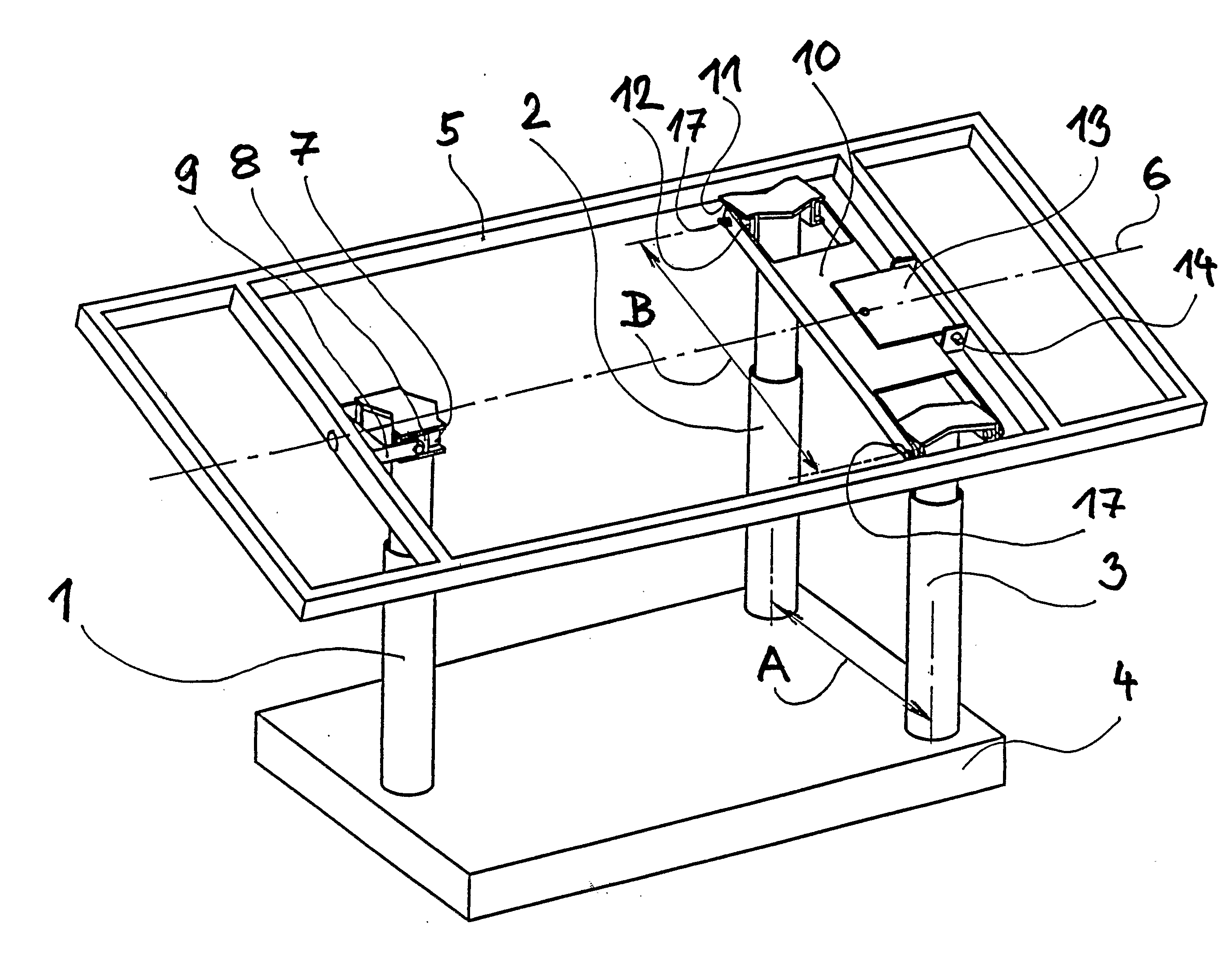
[0008]Such a design of the positioning mechanism of a bed reduces stressing of the lifters by horizontal components of the load, minimizes the installation height of the mechanism, makes it possible to tilt the patient surface frame from the bottom position of the lifters already as there is no danger of collision of the patient surface frame with the undercarriage frame.
[0010]In accordance with a preferred embodiment the distance between the axes of the pins arranged at the opposite ends of the arm is bigger than the distance between the longitudinal axes of the second and third lifter. This version reduces vertical forces loading the lifter during side loading of the patient surface, especially in case of a lateral tilt.
[0011]To facilitate movement control under the undercarriage frame and patient surface frame position sensors with an opposite cam are arranged. The use of such simple end sensors for the control of the zero position and the maximum tilt replaces complicated position measurements of each lifter.

Problems solved by technology

However, at such tilt there is a problem of collision of individual parts of the patient surface with the undercarriage.
For these reasons the used electronic installation is relatively complicated and the absolute position of the height of the patient surface must be sensed and collision statuses must be evaluated.
The use of more than two telescopic extensible lifters to control the height of the patient surface and its further positioning brings problems in the possibility of the mechanisms colliding in some positions.
Another disadvantage of this design is structural complexity and the resulting high investment demands of the existing tilting and positioning beds.
Another disadvantage of known solutions is the problematic combination of setting the side tilt and Trendelenburg and anti-Trendelenburg position, i.e. tilting the patient surface around the transversal axis.

Method used


Image

  • Positioning mechanism of a bed
  • Positioning mechanism of a bed
  • Positioning mechanism of a bed

Examples


Embodiment Construction

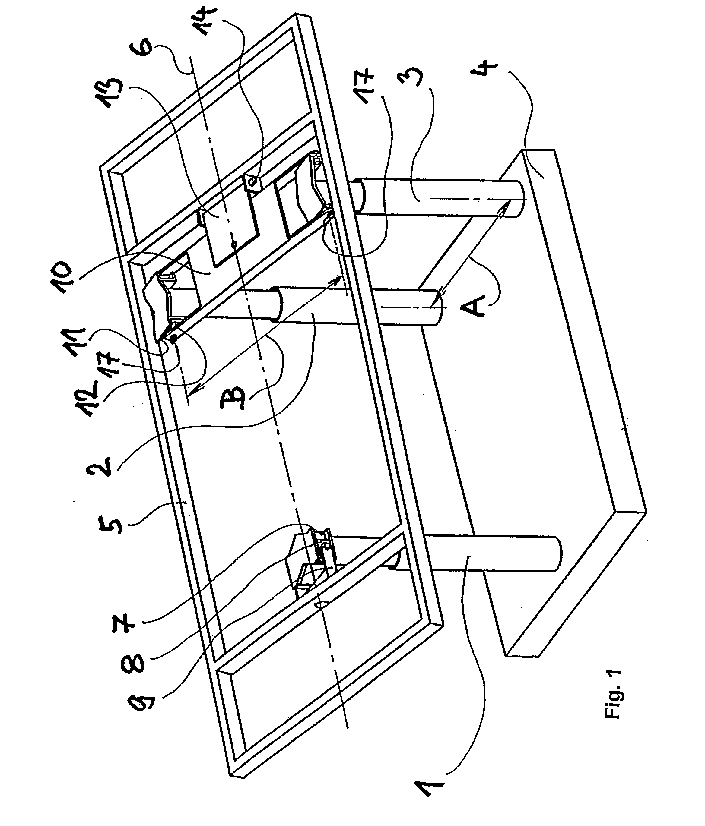
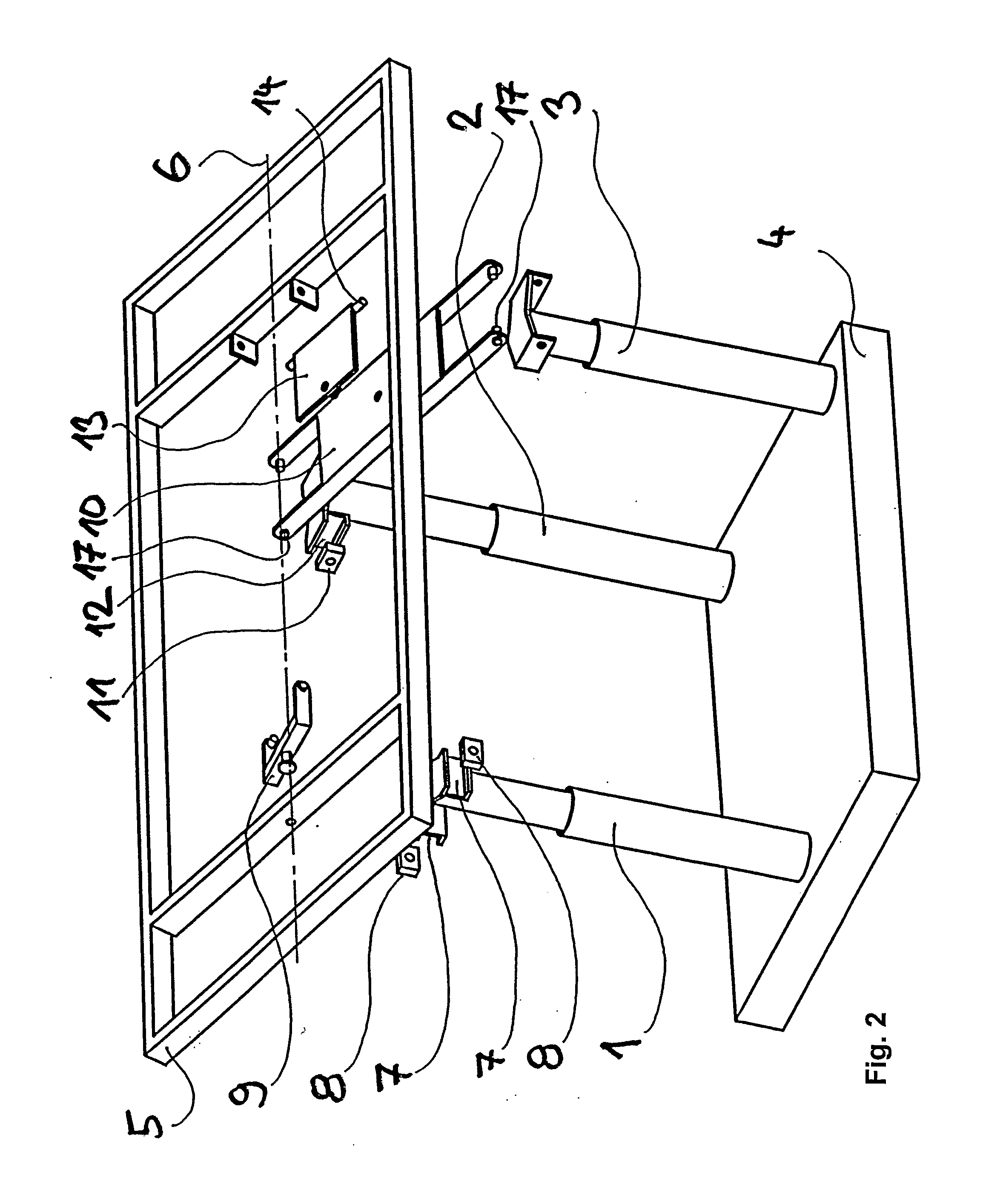
[0016]FIGS. 1 and 2 show a sample embodiment of the positioning mechanism of a bed in accordance with the invention comprising three height adjustable lifters 1, 2, 3 that are mounted on the undercarriage frame 4 at one side and at the other side are connected to the frame 5 of the patient surface of the bed.

[0017]The lifters 1, 2, 3 are height adjustable with the use of electric motors that are not shown here.

[0018]The lifters 1, 2, 3 can have any design know from the art. As an example the telescopic lifter described in the utility model no. CZ6654 can be mentioned.

[0019]The first lifter 1 is arranged on the undercarriage frame 4 vertically in such a way that the axis of the first lifter 1 intersects the longitudinal axis 6 of the patient surface frame 5. The first lifter 1 carries at its top end two horizontal first guides 7 in which two first sliders 8 are mounted in a sliding way. The first two sliders 8 are connected in a swinging way with the use of pins to the opposite arms ...


PUM


Abstract

A positioning mechanism of a bed comprising height adjustable lifters (1, 2, 3) that are mounted on the undercarriage (4) and connected to the patient surface frame (5). The first lifter (1) is arranged that its axis intersects the longitudinal axis (6) of the frame (5) and the said lifter (1) is connected to frame (5) oscillatingly around the longitudinal axis (6) of the frame (5) and in a sliding way in the direction of the longitudinal axis (6) of the frame (5). The second lifter (2) and the third lifter (2) are interconnected with an arm (10), oriented transversally to the longitudinal axis (6). The arm (10) is oscillatingly connected to the frame (5) and is connected at one end to the second lifter (2) both oscillatingly around an axis, in parallel with the longitudinal axis (6) of the frame (5) and in a sliding way transversally to the frame (5). At the other end the arm (10) is connected to the third lifter (3), oscillatingly around the axis, in parallel with the longitudinal axis (6) of the frame (5).

Description

TECHNICAL FIELD[0001]The invention relates to a positioning mechanism of a bed comprising at least two height adjustable lifters arranged in a distance from each other that are mounted on the undercarriage frame at one side and connected to the patient surface frame at the other side.BACKGROUND ART[0002]Within the care of lying patients it is advantageous if the hospital bed enables side tilt of the patient surface of the bed besides other positions. For therapeutic purposes a min. ±30° side tilt is required. However, at such tilt there is a problem of collision of individual parts of the patient surface with the undercarriage. To prevent a collision, it is usually necessary to lift the bed horizontally and only then it can be tilted sideways. Therefore, known tilting mechanisms usually raise the lowest possible position of the patient surface in the horizontal position. For these reasons the used electronic installation is relatively complicated and the absolute position of the hei...

Claims


Application Information

Patent Timeline
Patent Type & Authority Applications(United States)
IPC IPC(8): A61G7/008A61G7/005
CPCA61G7/005A61G7/012A61G7/008A61G2203/44
Inventor TESAR, MILANKOLAR, VLADMIR
Owner LINET SPOL
Learn More