Heat sink connector pin and assembly

a technology of heat sink and connector pin, which is applied in the direction of screws, threaded fasteners, electrical apparatus construction details, etc., can solve the problems of manual inserting of push pins, difficult removal, and inability to meet the needs of users,

Active Publication Date: 2018-10-30
ADVANCED MICRO DEVICES INC
View PDF17 Cites 0 Cited by
  • Summary
  • Abstract
  • Description
  • Claims
  • Application Information

AI Technical Summary

Benefits of technology

[0013]One or more advantages of the design includes, for example, a reduction in installation time and / or a reduction in the vertical force on a substrate reducing potential for hardware failure. In addition or alternatively, the heat sink connector pin may allow easier visual indication as to whether or not the pin is secured to the substrate and may only require access to a top surface of the substrate when inserting and removing the heat sink connector pin into a heat sink assembly.
[0020]In one example, two or more fingers serve as substrate bottom grips when they are extended in an outward position. Another surface of the pin assembly serves as a top side substrate stop surface so that a sleeve of the pin assembly does not pass through the through-hole and the movable fingers pass through in a retracted position and extend outwardly after passing through the opening in the substrate. If desired, a compression spring is used that provides downward pressure pushing the heat sink against the heat dissipating device and enhances shock absorption. In one example, the pin head is configured for a quarter turn or half turn causing the shaft to move in a downward position to cause the plurality of fingers to engage with the bottom of the substrate. In one example, the pin head has a shape so that the user can determine whether a heat sink connector pin is properly installed. Where a compression spring is employed, rotating or turning the pin head causes the compression of the spring which can further cause an upward force to be applied by the outwardly extended fingers, however any suitable structure may be employed.

Problems solved by technology

Electronic devices such as microprocessors, graphics processors, accelerated processing units or other electronic circuits may dissipate large amounts of heat when operating.
Push pins however can be manually intensive to insert and can be difficult to remove.
Such designs can require unnecessary amounts of force to insert the pin and are also typically not removable.
Problems also arise where the electronic device is fragile and forcing the angled tip through the hole of the substrate can unnecessarily cause damage to the electronic device and substrate.

Method used


Image

  • Heat sink connector pin and assembly
  • Heat sink connector pin and assembly
  • Heat sink connector pin and assembly

Examples


Embodiment Construction

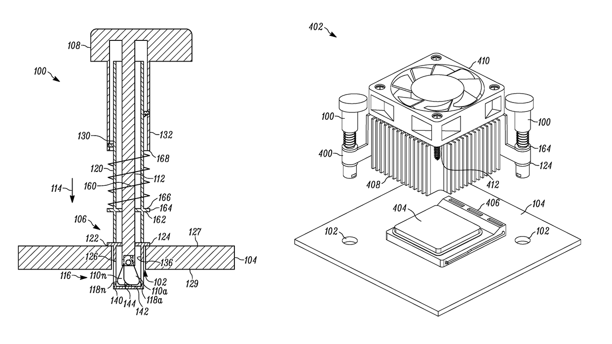
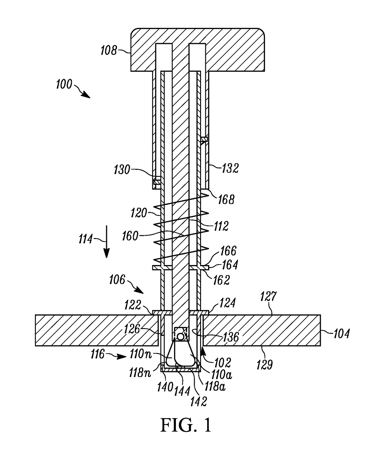
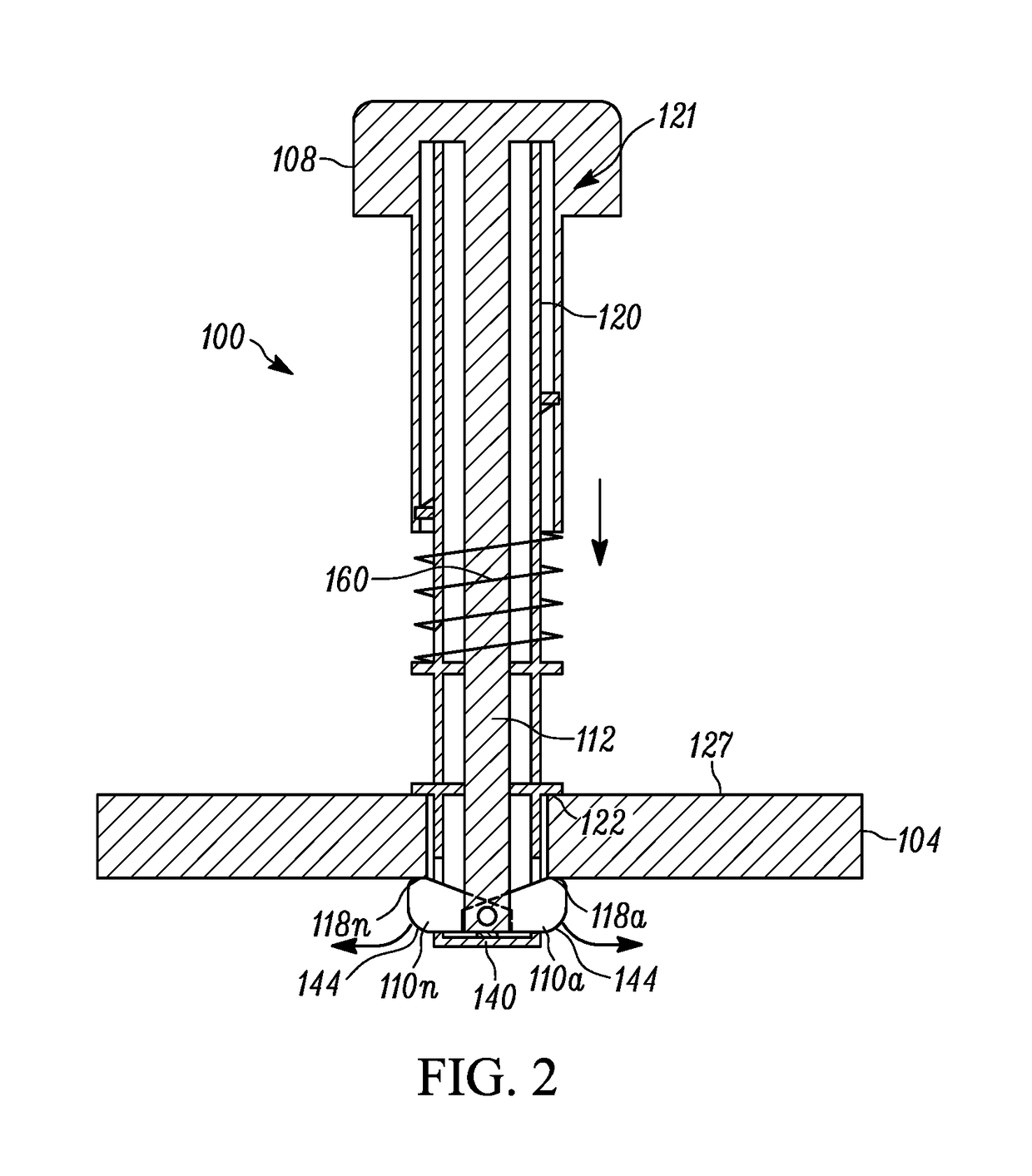
[0012]In one example, a heat sink connector pin includes a pin assembly with linkage that provides the movement of a pin head or cap in a downward movement to cause multiple movable fingers at an opposing end of the pin to move from a retracted position that allows insertion of the heat sink connector pin through an opening in the substrate, such as a through-hole, to mechanically move to an outward extended position so that the multiple fingers engage or grasp a bottom surface of the substrate. In one example, the pin head is rotatable in a twisting action to cause downward movement of a shaft structure to cause the fingers to move in an outward extended position to grasp the bottom surface of the substrate such as an integrated circuit socket or printed circuit board or any other suitable substrate. In other examples, any suitable force action may be employed other than a rotational or twisting motion that causes the shaft of the pin assembly to move in a downward motion to cause ...


PUM


Abstract

A heat sink connector pin includes a pin assembly with linkage that provides the movement of a pin head or cap in a downward movement to cause multiple movable fingers at an opposing end of the pin to mechanically move from a retracted position that allows insertion of the heat sink connector pin through an opening in the substrate, such as a through-hole, to move to an outward extended position so that the multiple fingers engage or grasp a bottom surface of the substrate. In one example, the movable fingers are rotatably connected to share a same rotational axis with each other. In one example, the pin assembly includes a sleeve adapted to receive the shaft structure and is adapted to engage with the pin head. The sleeve includes a substrate stop surface adapted to contact a top surface of the substrate during insertion of the pin through the substrate.

Description

FIELD OF THE DISCLOSURE[0001]The disclosure relates to pins that are used to attach heat sinks to substrates that support heat dissipating devices such as microprocessors, memory or other electronic circuits.BACKGROUND OF THE DISCLOSURE[0002]Electronic devices such as microprocessors, graphics processors, accelerated processing units or other electronic circuits may dissipate large amounts of heat when operating. The electronic devices are sometimes placed in sockets which are then soldered to substrates such as circuit boards. Heat sinks are then placed in thermal contact with outer surfaces of the device (such as the outer surface of the package) to draw heat away from the electronic device. Fans may also be employed as well in an attempt to keep the heat dissipating device cool.[0003]Heat sink attachment pins also referred to as connector pins are often used to attach the heat sink to the substrate when it is placed on top of or under the electronic device. Some heat sink connect...

Claims


Application Information

Patent Timeline
Patent Type & Authority Patents(United States)
IPC IPC(8): H05K7/20H01L23/40F16B21/12H05K1/02
CPCH05K7/2049H05K1/0203H05K7/20154H05K2201/09063H01L23/4006H05K2201/066F16B21/12F16B5/0266F16B19/109H01L23/4093H01L23/40H01L23/3675H01L23/3672
Inventor LAMBERT, DONALD L.
Owner ADVANCED MICRO DEVICES INC
Why Eureka
Try Eureka