Tiltrotor controlled by double-propeller vertical duct
What is Al technical title?
Al technical title is built by PatSnap Al team. It summarizes the technical point description of the patent document.
A technology of double propellers and tilting rotors, which is applied in the direction of rotorcraft, aircraft, motor vehicles, etc., can solve the problems of short control force arm, complex control mode, and complex structure of periodic pitch change mechanism, etc., to reduce the size of the duct , the effect of reducing flight resistance
Inactive Publication Date: 2012-06-06
BEIHANG UNIV
View PDF0 Cites 0 Cited by
Summary
Abstract
Description
Claims
Application Information
AI Technical Summary
This helps you quickly interpret patents by identifying the three key elements:
Problems solved by technology
Method used
Benefits of technology
Problems solved by technology
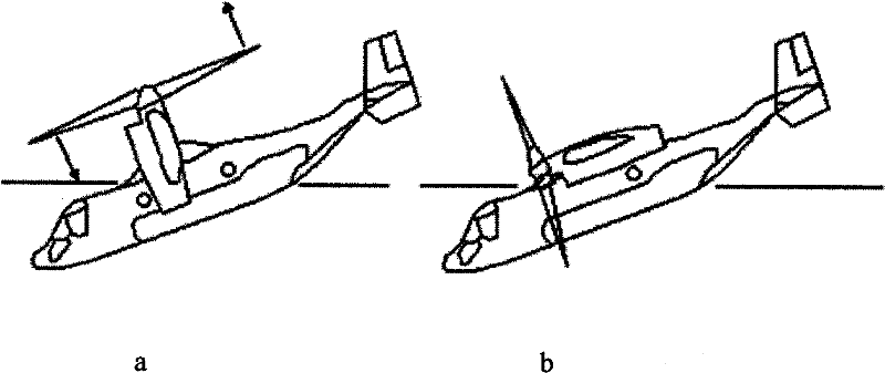
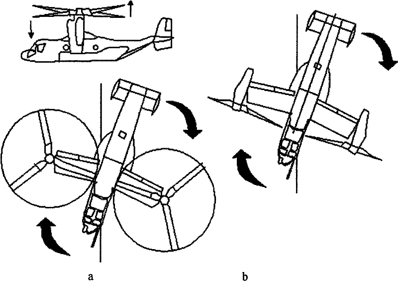
[0009] It can be seen from the control method of the tiltrotor aircraft represented by the V22 to control the vertical flight and switch the flight mode by periodic pitch change that all attitude control is based on periodic control when the efficiency of the aircraft control rudder surface is insufficient. Variable distance to control, the control method is complex
When using cyclic pitch control to control the longitudinal attitude, it will cause the coupling effect of the aircraft flying forward
Moreover, the structure of the periodic variable pitch mechanism is complex, and the complex structure and control methods are detrimental to the safety and reliability of the tilt rotor aircraft.
At the same time, the attitude of the aircraft is controlled by the periodic pitch change method. Due to the short arm of the control force, the efficiency of generating the control torque is not high.
Method used
Image
Click on the blue label to locate the original text in one second.
Reading with bidirectional positioning of images and text.
Examples
Embodiment Construction
[0058] See Figure 4 ~ Figure 8 Shown, the present invention uses a kind of tilt rotor aircraft controlled by double propeller vertical duct, this aircraft adopts the design of side by side double rotor, conventional aerodynamic layout, and it is made of fuselage 1, straight wing 2, rotor 3, short Cabin 4, aileron 5, vertical tail 6, rudder 7, elevator 8, horizontal tail 9, landing gear 10, power and deceleration system 11 and double propeller vertical duct structure 12. The straight wing 2 is installed on both sides of the middle section of the fuselage 1, the rotor 3 is installed on the end of the nacelle 4, the main body of the landing gear 10 is located at the belly of the fuselage 1, and the straight wings 2 on both sides of the fuselage 1 support the The nacelle 4 at the end, the aileron 5 is connected to the outside of the wing 2, the horizontal stabilizer 9 is connected to the tail of the fuselage 1, the elevator 8 is connected to the rear of the horizontal stabilizer ...
PUM
Abstract
The invention provides a tiltrotor controlled by a double-propeller vertical duct. The tiltrotor, using the design of parallel twin-rotor and conventional aerodynamic configuration, consists of a fuselage, straight wings, rotors, a nacelle, an aileron, a vertical empennage, a rudder, an elevator, a horizontal empennage, a duct end cover, a vertical duct, an undercarriage, a power and decelerationsystem, a propeller power input shaft, a lower propeller, an upper propeller, louver-type slipstream sheets, a propeller gearing and collective-pitch controlling device, a propeller gear box supporting structure, a duct end cover driving device, a duct end cover motion slide rail and a slipstream sheet controlling device. Compared with the cyclic pitch control mode, the tiltrotor of the inventionsimplifies the operations during the vertical flight and the flight conversion and improves the reliability by using the structure of the double-propeller vertical duct to control the vertical flightand the conversion of the flight mode, and the tiltrotor has the advantages of long control force arm, high control efficiency and simple structure. Therefore, the tiltrotor constitutes a novel aircraft with significant development potential and promising future.
Description
(1) Technical field [0001] The invention relates to a tilt-rotor aircraft, in particular to a tilt-rotor aircraft controlled by a double-propeller vertical duct, and belongs to the technical field of aviation vehicle design. (2) Background technology [0002] A tiltrotor aircraft combines features of a helicopter and a fixed-wing aircraft. Compared with fixed-wing aircraft, this type of aircraft can take off and land vertically, without relying on the airport runway, and can achieve hovering and low-speed forward flight; compared with traditional helicopters, tilt-rotor aircraft have greater cruising speed and range , the lift generated by the wings in the cruising process is more economical than the helicopter, so this kind of aircraft has been widely concerned since its birth. The earliest and most systematic research on tilt rotor aircraft is the United States. After decades of research, demonstration and testing, the United States has developed the V22, a representative...
Claims
Application Information
Patent Timeline
Application Date:The date an application was filed.
Publication Date:The date a patent or application was officially published.
First Publication Date:The earliest publication date of a patent with the same application number.
Issue Date:Publication date of the patent grant document.
PCT Entry Date:The Entry date of PCT National Phase.
Estimated Expiry Date:The statutory expiry date of a patent right according to the Patent Law, and it is the longest term of protection that the patent right can achieve without the termination of the patent right due to other reasons(Term extension factor has been taken into account ).
Invalid Date:Actual expiry date is based on effective date or publication date of legal transaction data of invalid patent.