Belt tensioner

a belt tensioner and belt technology, applied in the direction of safety belts, pedestrian/occupant safety arrangements, vehicular safety arrangements, etc., can solve the problem of limited mounting space in the confinement of vehicles

Active Publication Date: 2011-01-20
TRW AUTOMOTIVE GMBH
View PDF9 Cites 8 Cited by
  • Summary
  • Abstract
  • Description
  • Claims
  • Application Information

AI Technical Summary

Benefits of technology

[0013]Preferably, the deflector divides the tension transmitting means into a linear portion at the drive side, a linear portion at the coupling member side and a bent deflecting portion located there between. In this way

Problems solved by technology

The limited mounting space in a vehicle confi

Method used


Image

  • Belt tensioner
  • Belt tensioner
  • Belt tensioner

Examples


Embodiment Construction

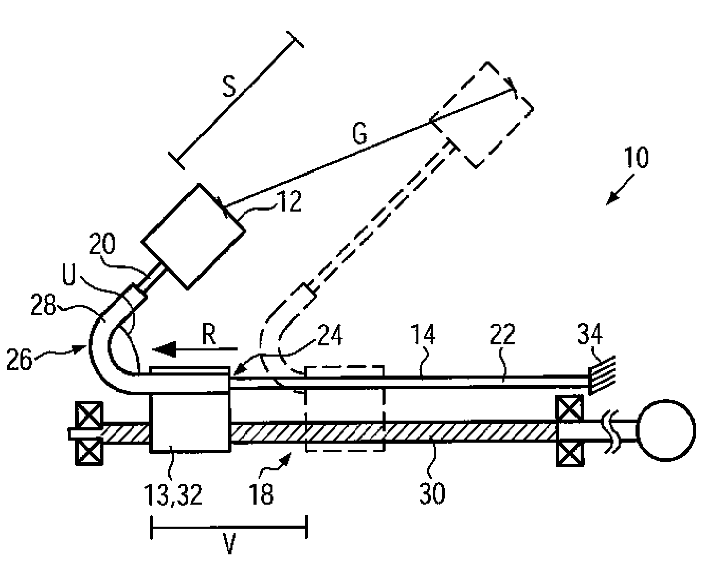
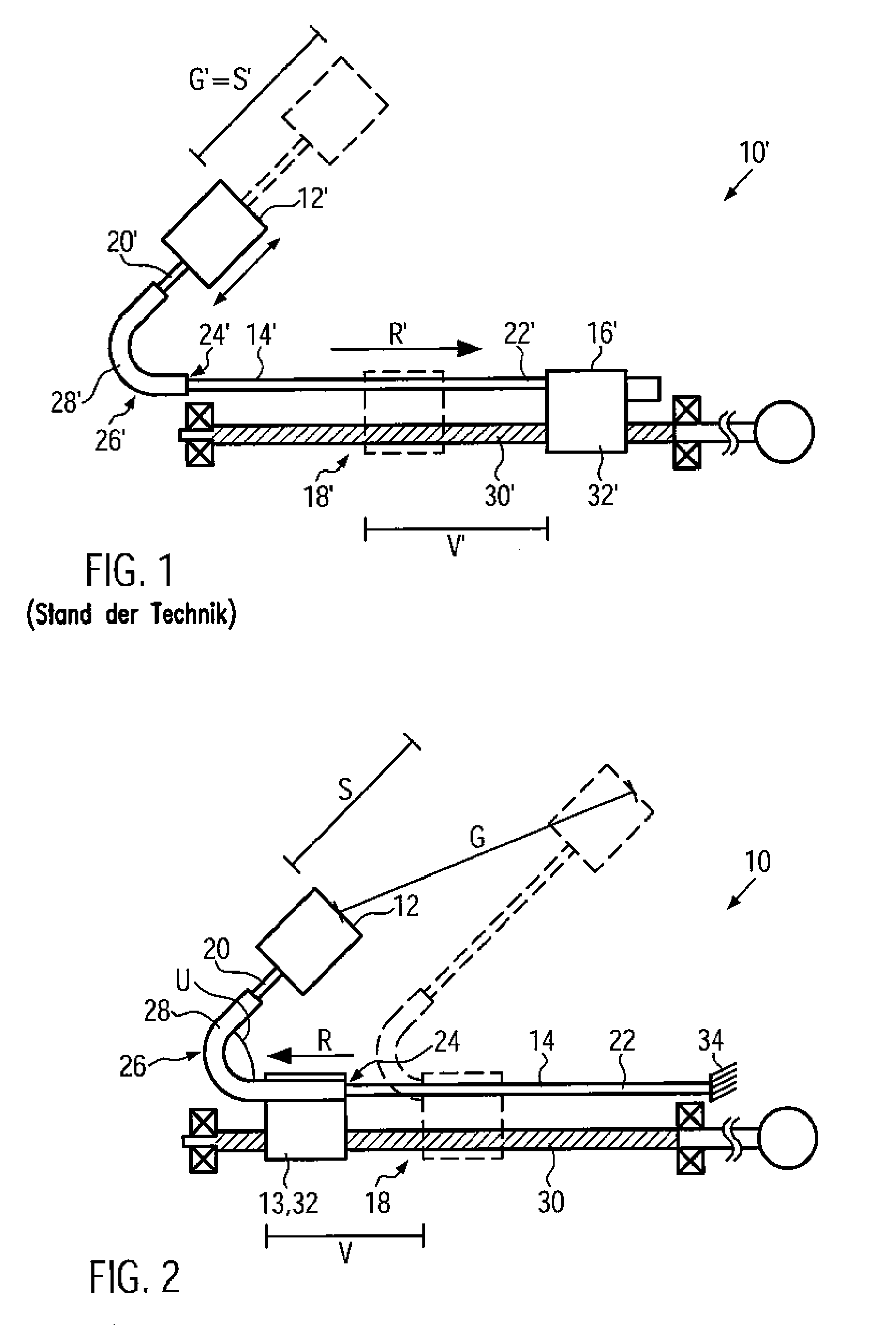
[0017]In FIG. 1 a belt tensioner 10′ known from the state of the art is shown. The belt tensioner 10′ includes a coupling member 12′, a belt buckle in this case, to which a vehicle seat belt not shown here can be fastened. The coupling member 12′ is held at a flexible tension transmitting means 14′ fixed to a catch 16′ of a drive unit 18′. The tension transmitting means 14′ in this case is a steel cable having a first linear portion 20′ connected to the coupling member 12′ and a linear mounting portion 22′ to which the catch 16′ is mounted. The tension transmitting means 14′ is deflected in a deflecting portion 24′ positioned between the first portion 20′ and the mounting portion 22′ by a deflector 26′ fixed to the vehicle.

[0018]The deflector 26′ includes a guide 28′ in the form of a tube in this case on or in which the tension transmitting means 14′ is supported to be longitudinally displaceable and which deflects the tension transmitting means 14′ in the direction of the coupling ...


PUM


Abstract

A belt tensioner of a vehicle occupant restraint system, especially a belt buckle tensioner, comprises a coupling member (12) to the vehicle seat belt, a drive unit (18), a flexible tension transmitting means (14) and a deflector (26). The flexible tension transmitting means (14) is connected at least indirectly to the coupling member (12) and is moved via the drive unit (18) in the event of tensioning. The deflector (26) deflects the tension transmitting means (14) in the direction of the coupling member (12). The tension transmitting means (14) is moved along the deflector (26) in the event of tensioning. According to the invention, the drive unit (18) is coupled in terms of drive to the deflector (26) such that the drive unit (18) moves the deflector (26) upon activation and thus displaces the coupling member (12) in the tensioning direction (R).

Description

FIELD OF THE INVENTION[0001]The invention relates to a belt tensioner of a vehicle occupant restraint system, especially a belt buckle tensioner, comprising a coupling member to the vehicle seat belt, a drive unit, a flexible tension transmitting means and a deflector for the tension transmitting means.BACKGROUND OF THE INVENTION[0002]Belt tensioners serve for eliminating a belt slack in the case of strong deceleration so that the vehicle occupant can more quickly take part in the overall deceleration of the vehicle. A buckle tensioner includes a flexible tension transmitting means, for instance a steel cable, to which a belt buckle of a seat belt is fastened. The tension transmitting means is mounted to a drive unit and is deflected toward the belt buckle via a deflection fixed to the vehicle. When activating the drive unit, the latter pulls the tension transmitting means through the deflector so that the belt buckle fastened to the tension transmitting means is pulled in the direc...

Claims


Application Information

Patent Timeline
IPC IPC(8): B60R22/195
CPCB60R22/1951B60R2022/1957B60R22/1952
Inventor MAGES, MARK
Owner TRW AUTOMOTIVE GMBH
Why Eureka
Try Eureka