Lighting apparatus

Inactive Publication Date: 2011-01-20
EYE LIGHTING INT OF NORTH AMERICA
View PDF42 Cites 22 Cited by
  • Summary
  • Abstract
  • Description
  • Claims
  • Application Information

AI Technical Summary

Benefits of technology

[0038]As described above, the lighting apparatus of the invention has the heat dissipation fins extending upwardly from the base, and an air channel exists between any two adjacent heat dissipation fins and communicates with the openings of the base. Consequently, the heat generated by the LED module disposed on the lower surface of the base can be dissipated by thermal-conduction and thermal-convection. As a result, the heat dissipation efficiency of the lighting apparatus is improved.

Problems solved by technology

More specifically, electrons and holes in the semiconductor material are combined to release excessive energy in the form of light when a current is applied to the semiconductor material.
Generally speaking, high-power LEDs all encounter a heat dissipation problem.
When an LED is operated at an overly high temperature, the brightness of the LED lamp may be reduced and the lifespan of the LED may be shortened.

Method used


Image

  • Lighting apparatus
  • Lighting apparatus
  • Lighting apparatus

Examples


Embodiment Construction

[0049]Reference will now be made in detail to the present preferred embodiments of the invention, examples of which are illustrated in the accompanying drawings. Wherever possible, the same reference numbers are used in the drawings and the description to refer to the same or like parts.

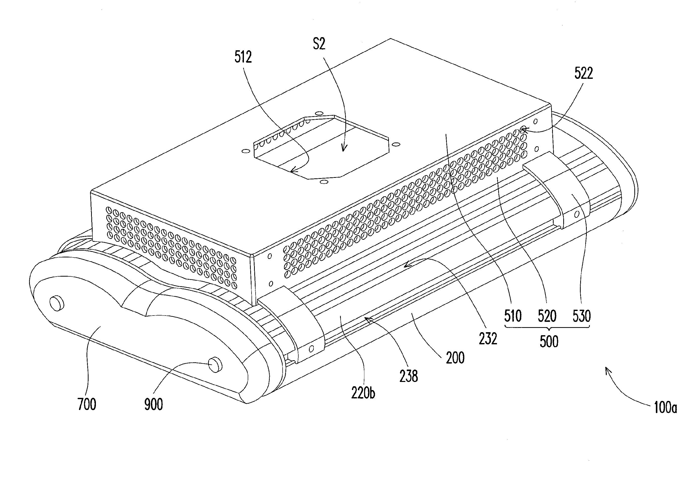
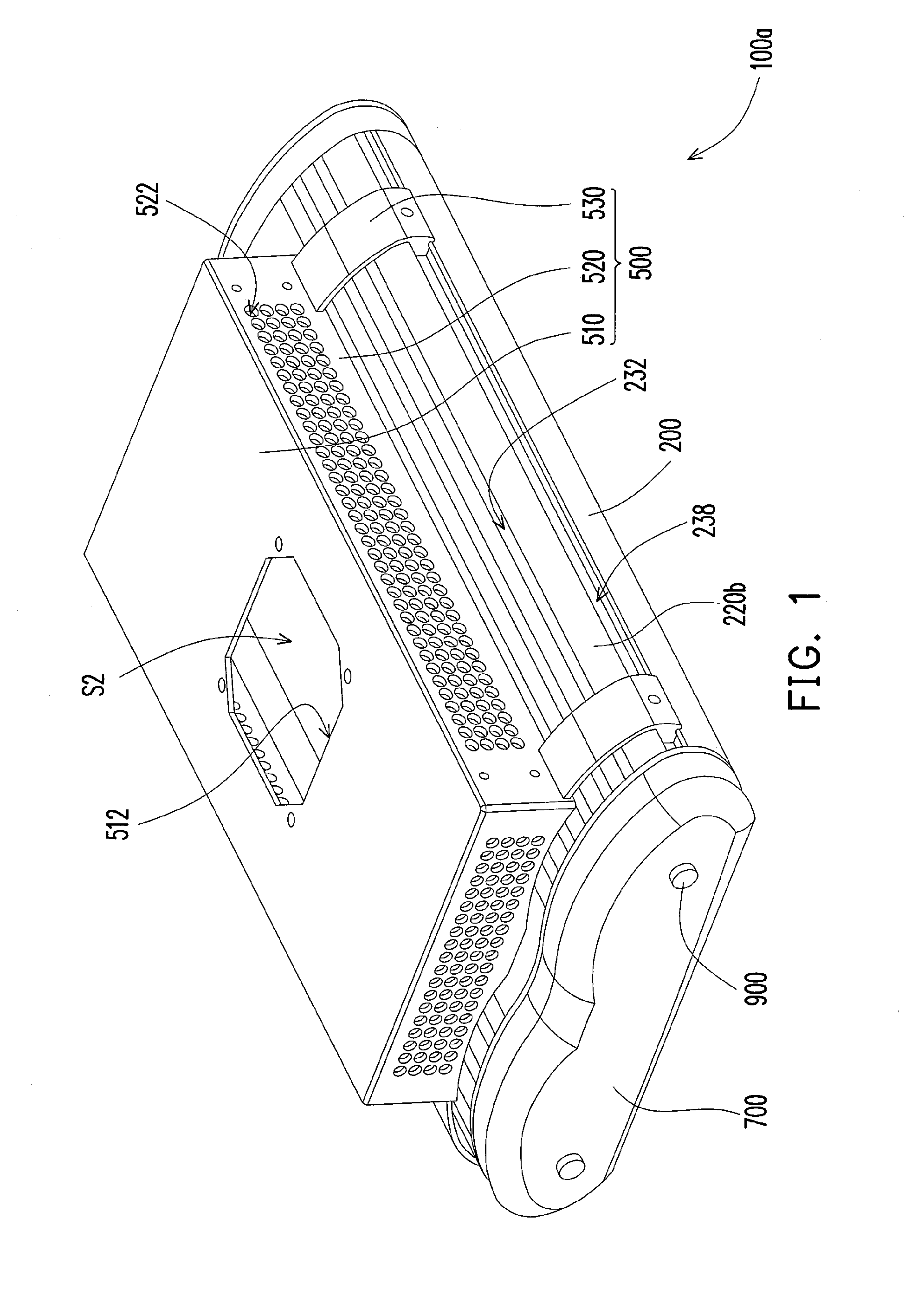
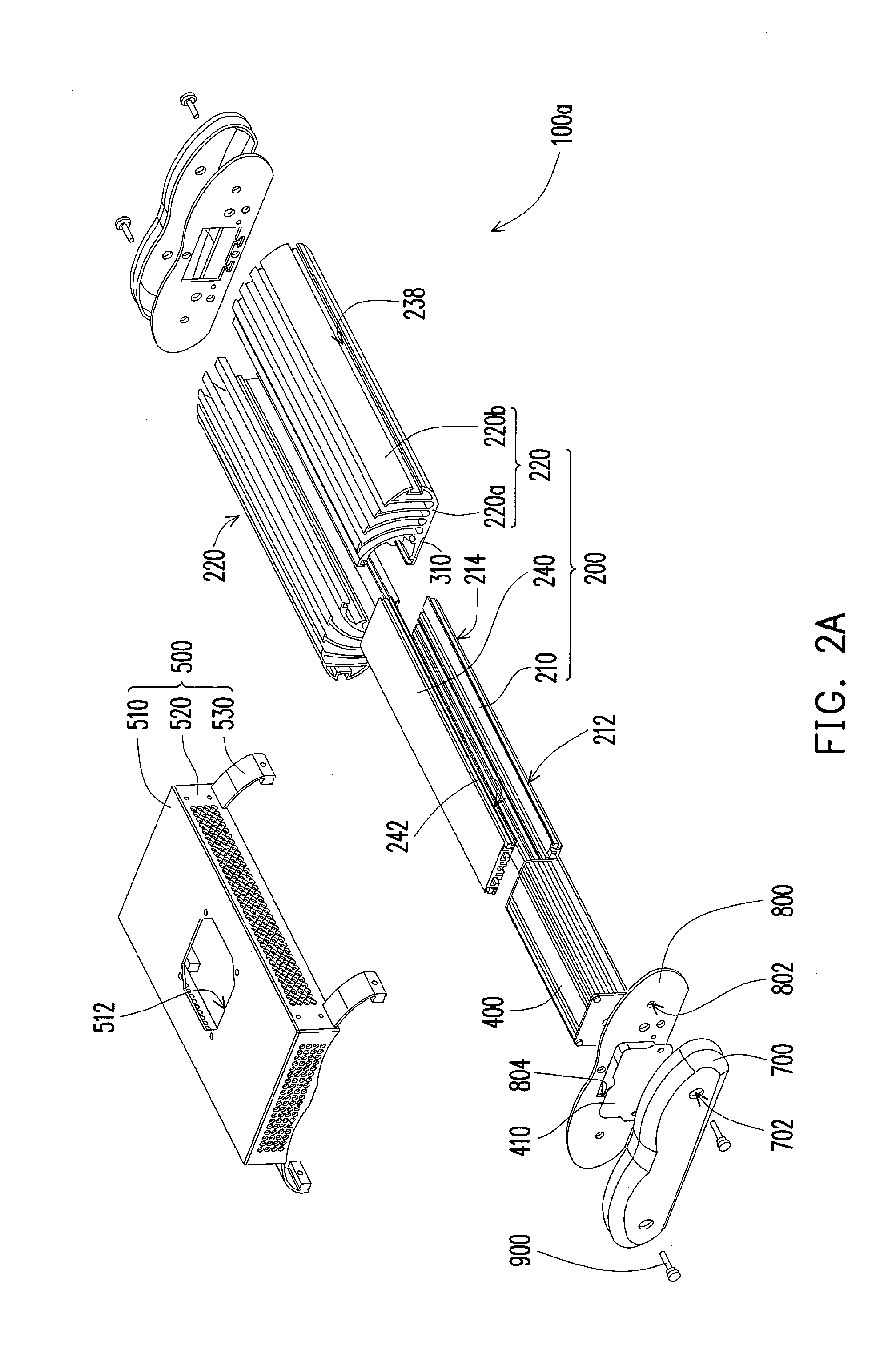
[0050]FIG. 1 is a schematic perspective view of a lighting apparatus according to one embodiment of the invention; FIG. 2A is a schematic exploded view of the lighting apparatus in FIG. 1; FIG. 2B is a partially enlarged view of the heat sink of the lighting apparatus in FIG. 2A; FIG. 2C is a partially enlarged view of the first connection element of the lighting apparatus in FIG. 2A; FIG. 2D is a schematic perspective view of the heat dissipation module of the lighting apparatus in FIG. 2A. Referring to FIG. 1 and FIG. 2B at first, in this embodiment, a lighting apparatus 100a including a heat dissipation module 200 and a light-emitting diode (LED) module 300 is provided.

[0051]To be more specific, w...


PUM


Abstract

A lighting apparatus includes a heat dissipation module and a light-emitting diode (LED) module. The heat dissipation module comprises heat sinks assembling each other, and each heat sink comprises air channels formed therein for air convection. The LED module is mounted on at least one of the heat sinks

Description

CROSS-REFERENCE TO RELATED APPLICATION[0001]This application claims the priority benefit of U.S. provisional application Ser. No. 61 / 225,712, filed on Jul. 15, 2009. The entirety of the above-mentioned patent application is hereby incorporated by reference herein and made a part of this specification.BACKGROUND OF THE INVENTION[0002]1. Field of the Invention[0003]The present invention generally relates to a lighting apparatus, and in particular, to a lighting apparatus having more efficient heat dissipation.[0004]2. Description of Related Art[0005]A light-emitting diode (LED) is a semiconductor device that is fabricated by using a compound of chemical elements selected from the groups III-V, such as GaP, GaAs, and so forth. This kind of semiconductor material has the property of converting electrical energy into light. More specifically, electrons and holes in the semiconductor material are combined to release excessive energy in the form of light when a current is applied to the se...

Claims


Application Information

Patent Timeline
IPC IPC(8): F21S4/00F21V29/00
CPCF21S8/086F21V15/013F21V29/004F21V29/83F21Y2101/02F21V29/71F21V29/74F21W2131/103F21Y2115/10
Inventor LITTLE, JR., WILLIAM D.
Owner EYE LIGHTING INT OF NORTH AMERICA
Why Eureka
Try Eureka