Luminaires comprising waveguides

Inactive Publication Date: 2010-06-24
SNAPTRACK
View PDF17 Cites 22 Cited by
  • Summary
  • Abstract
  • Description
  • Claims
  • Application Information

AI Technical Summary

Benefits of technology

[0008]At least some embodiments are based at least partially on a recognition that there exists an unsatisfied need for novel configurations of architectural lighting that offer improvements in form factor and / or improvements in efficiency in conversion of electrical energy to desired illumination. For example, some embodiments provide a flat panel configuration having a particularly thin thickness dimension. Some embodiments include a waveguide that more efficiently and evenly distributes light from a light source. Some embodiments include a plurality of turning features such that generated light can be preferentially directed in one or more selected directions to more efficiently direct the generated light to a desired illumination target. Some embodiments provide for more efficient heat dissipation.

Problems solved by technology

While the thickness of panel lighting is generally significantly less than corresponding width and length dimensions, it is frequently the case that the thickness of existing panel lighting forces limitations in installation and use.
While this is a commonly employed technique for architectural lighting, it nevertheless requires time and materials for forming the recess and requires placement or removal of materials that might otherwise occupy the recess area to avoid interference with the panel lighting fixture.
Such an installation is frequently incompatible with many vertical building structures, such as interior or exterior walls of a building.
Structural components such as joists and studs cannot readily be removed without compromising the strength of the corresponding structural member.
A further drawback to certain existing architectural lighting configurations is that they exhibit low efficiency in conversion of electrical energy to visible light.
Such configurations do not efficiently convert the total electrical power used to desired illumination.

Method used


Image

  • Luminaires comprising waveguides
  • Luminaires comprising waveguides
  • Luminaires comprising waveguides

Examples


Embodiment Construction

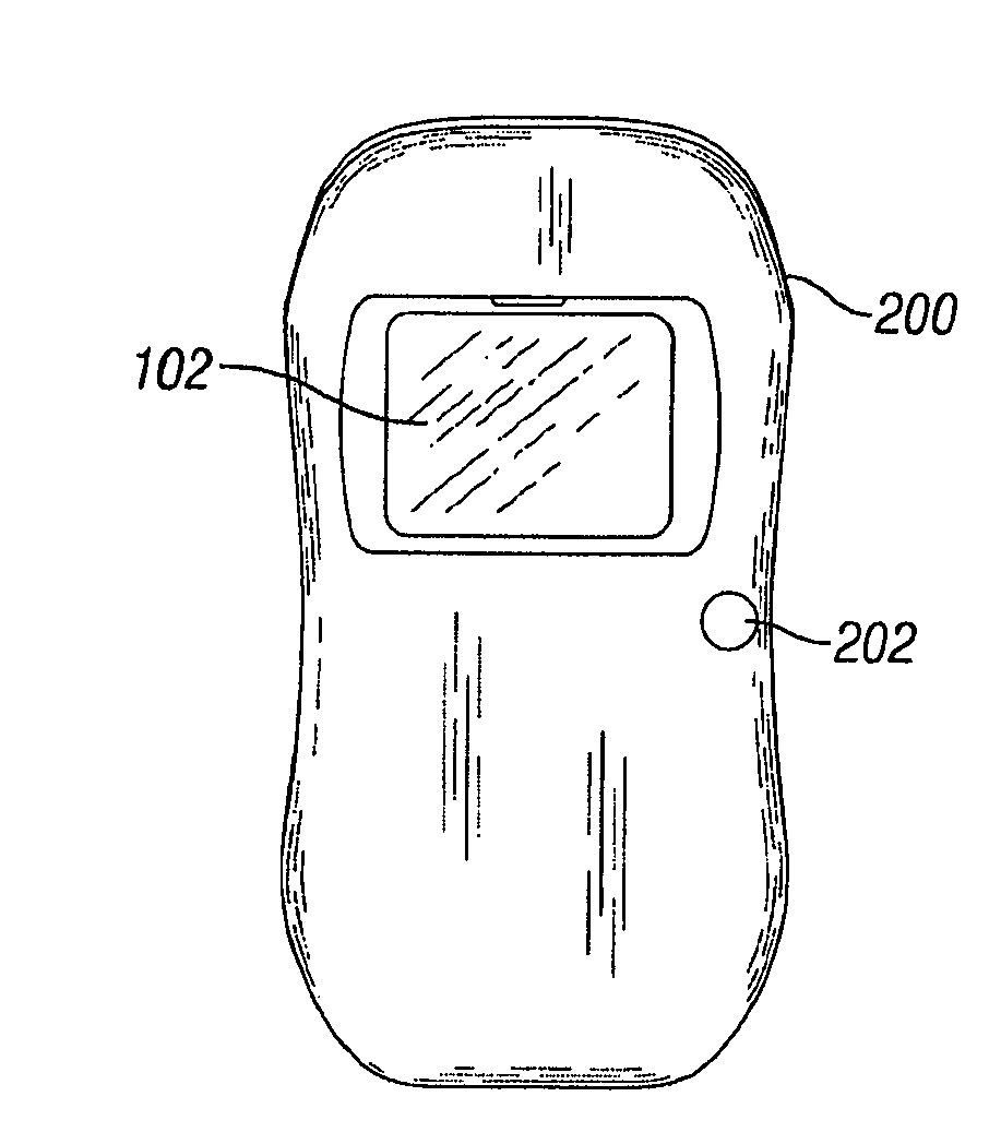
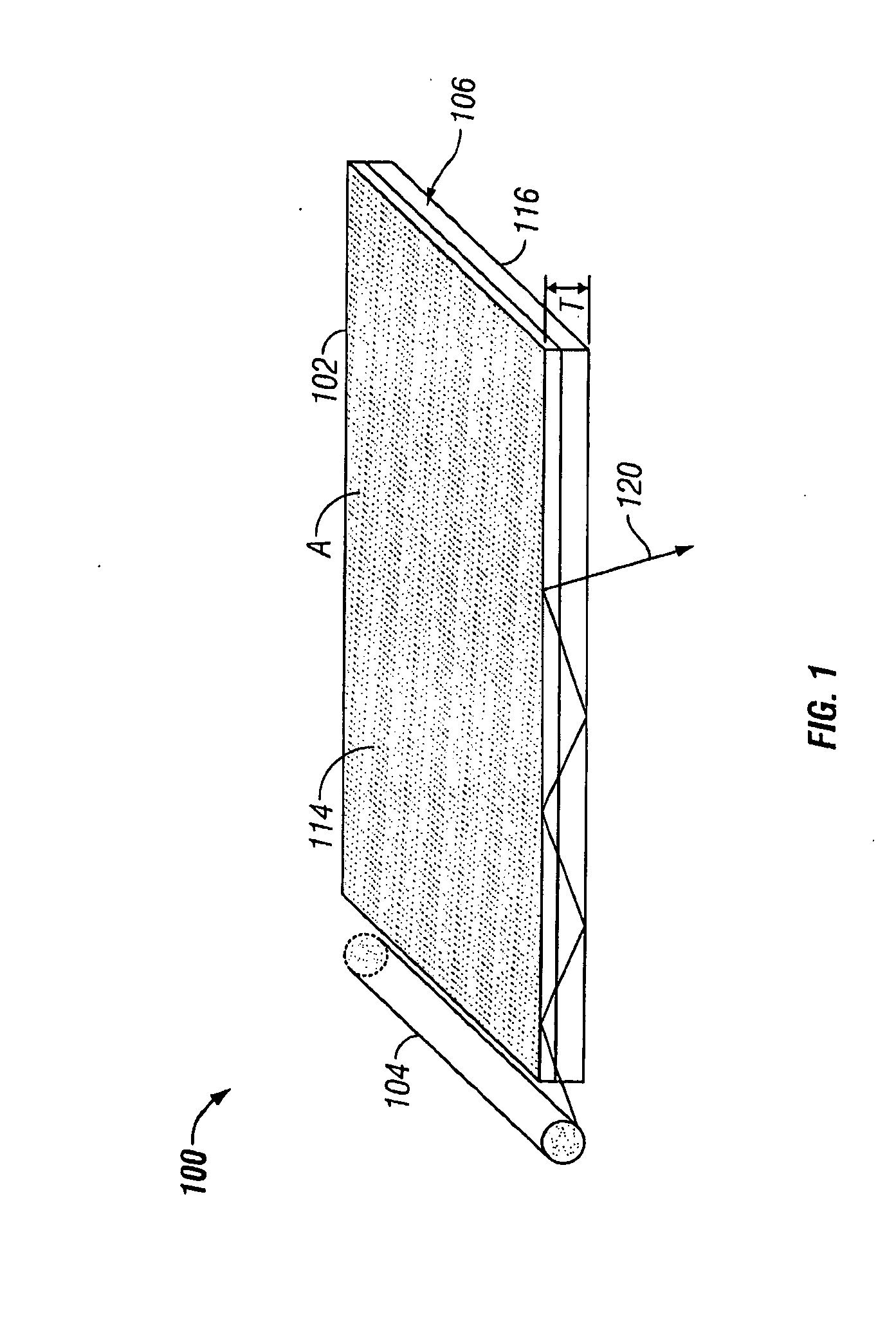
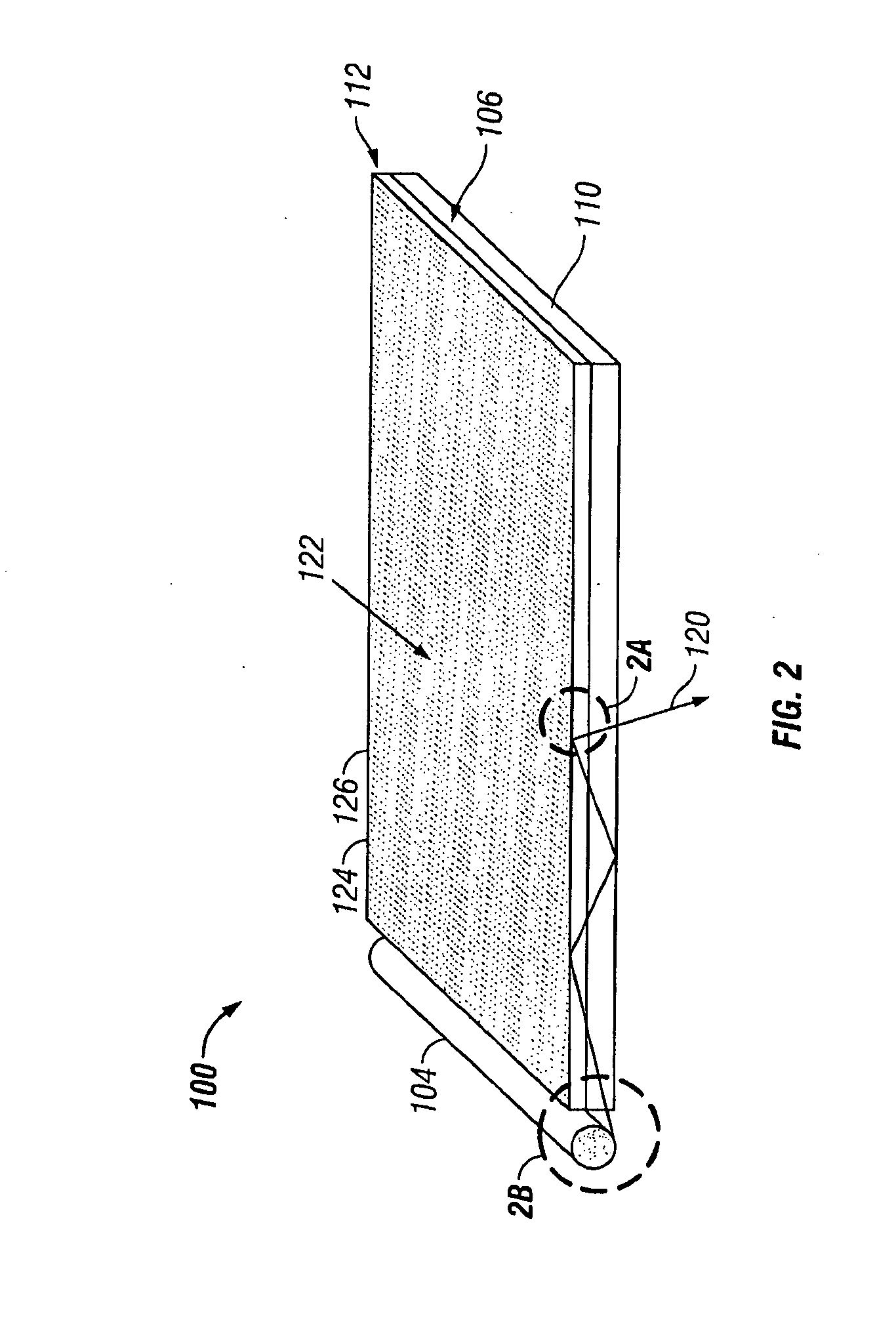
[0027]The following detailed description is directed to certain specific embodiments of the invention. However, the invention can be embodied in a multitude of different ways. In this description, reference is made to the drawings wherein like parts are designated with like numerals throughout. FIG. 1 provides a perspective schematic view of one embodiment of a lighting assembly 100 such as an architectural lighting assembly. The architectural lighting assembly 100 is configured to generate and direct light for artificial illumination of a desired area or volume.

[0028]The lighting assemblies 100 include one or more luminaires 102. The luminaires 102 are configured to generate and emit light in one or more selected light emission directions 120 as will be described in greater detail below. The lighting assemblies 100 and luminaires 102 generally comprise one or more light sources 104. The light sources 104 can be based on any of a variety of light source technology including but not ...


PUM


Abstract

In certain embodiments, architectural lighting comprises a luminaire with a light source and a waveguide having forward and rearward surfaces. The waveguide can be disposed with respect to the light source such that light from the light source is input into the waveguide and guided therein. The waveguide can include a plurality of turning features that turn the light guided within the waveguide out the forward surface and one or more mounting fixtures for mounting the luminaire on an architectural structure. Some embodiments include a luminaire comprising a light source, a waveguide, turning features, and a lamp stand. Other embodiments are also described.

Description

BACKGROUND[0001]1. Field of the Invention[0002]The invention relates to the field of lighting and includes a luminaire with a light guide that can provide a thin form factor and improved light production efficiency.[0003]2. Description of the Related Art[0004]A variety of architectural lighting configurations are utilized to provide artificial illumination in a wide variety of indoor and / or outdoor locations. Such configurations can include fixed and portable architectural lighting. Various configurations can employ technologies such as incandescent, fluorescent, and / or light emitting diode based light sources.[0005]One type of architectural lighting configuration can be referred to generally as panel lighting. Panel light may include for example fluorescent lighting in a light box behind a plastic lenticular panel. Panel lighting is often configured as planar and square or rectangular and having width and length dimensions significantly greater than a thickness dimension. While the...

Claims


Application Information

Patent Timeline
IPC IPC(8): B60Q1/00F21V33/00
CPCF21V33/006G02B6/0095G02B6/0016F21S6/00F21S8/033F21S8/04
Inventor GRUHLKE, RUSSELL WAYNE
Owner SNAPTRACK
Why Eureka
Try Eureka