Variable gain control for high speed receivers

a receiver and variable gain technology, applied in gain control, multi-frequency code system, instruments, etc., can solve the problems of receivers with sub-optimal dynamic range, signal-to-noise ratio problems, and not necessarily enough accuracy or range to properly select the gain

Inactive Publication Date: 2011-01-20
ANRITSU CO
View PDF10 Cites 26 Cited by
  • Summary
  • Abstract
  • Description
  • Claims
  • Application Information

AI Technical Summary

Benefits of technology

[0010]Embodiments of the present invention provide methods and systems to overcome the problems with making gain ranging decisions in previous high speed receiver environments.

Problems solved by technology

The former often does not necessarily have enough accuracy or range to properly select the gain and the latter can take too much time since a full measurement cycle must be repeated when a gain change is made.
If the variable gain of amplifier 104 is set too low, then the receiver will have sub-optimal dynamic range and signal-to-noise ratios can be a problem.
If the variable gain is set too high, there can be compression of the amplifiers or distortion of the A / D converter and signal.
In both cases, the dynamic range of the receiver would be compromised.
In some cases, using primarily analog hardware to determine or measure the state of the IF signal to enable performing the gain ranging is not desired since the thresholds of the analog components used to check and reset gain levels may not be stable over time and temperature, or the decision process may be too slow for a high speed receiver.
In addition, there may be synchronization issues between the analog circuits and the digital data acquisition process that require additional complexity to resolve.
Such synchronization issues can also slow down the overall measurement process when a gain change is required.
There may also be further complications if the incoming signal is spectrally complex in that the decision to change gain may be based on some attribute (e.g., total power) rather than the desired attribute (e.g., power at a specific frequency).
A disadvantage of the scenario of FIG. 2 is that in some cases the entire measurement cycle must be completed before it is known whether the gain has to be adjusted.
Time delays during the gain ranging decision process itself may be important since the decision / gain change / settling process is serial in nature.
These time penalties may be particularly troubling in a high speed receiver.

Method used


Image

  • Variable gain control for high speed receivers
  • Variable gain control for high speed receivers
  • Variable gain control for high speed receivers

Examples


Embodiment Construction

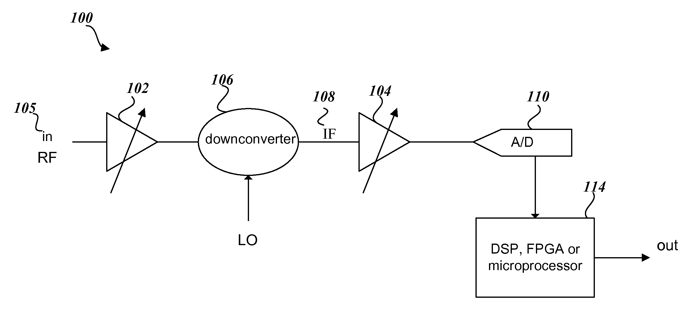
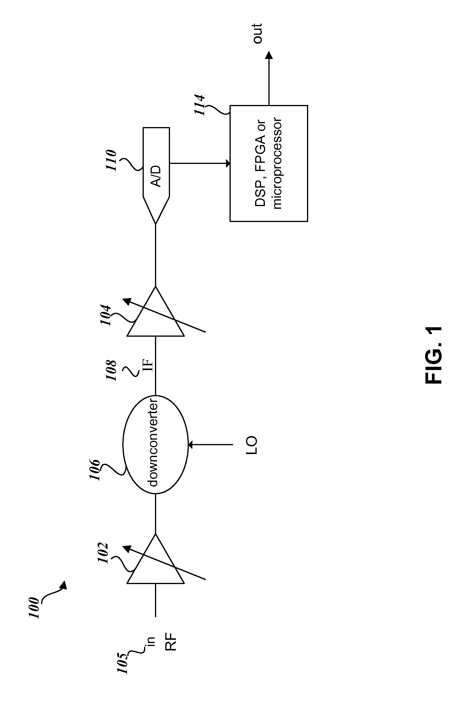
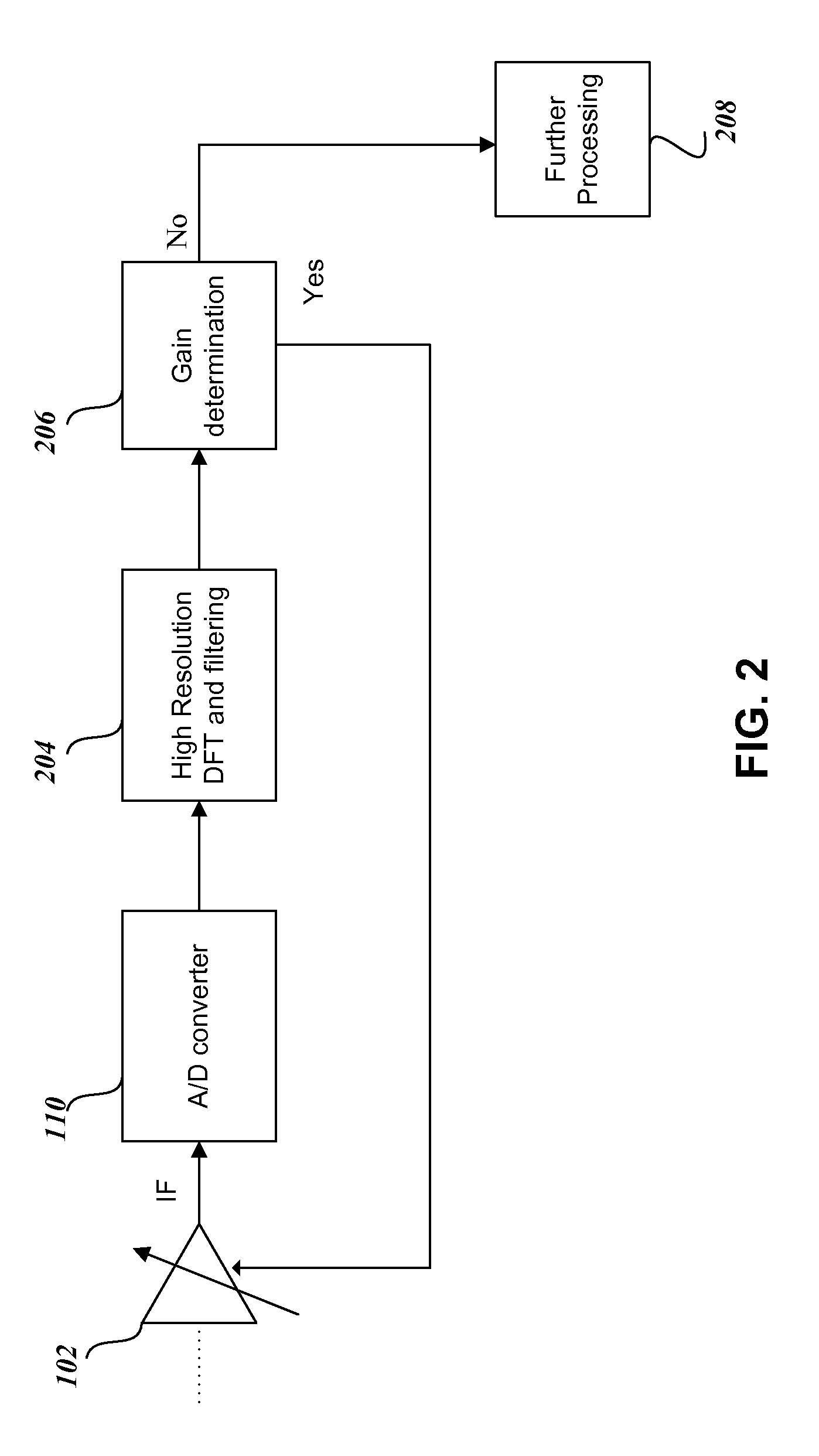
[0020]FIG. 3 illustrates components of a receiver system 300 for determining gain ranging decisions in a high speed receiver environment according to embodiments of the present invention. The receiver 300 includes a variable gain amplifier 302. The variable gain amplifier 302 can, e.g., receive the intermediate frequency (IF) output 312 from a downconverter (not shown) of a receiver that has a variable gain input (the output from the downconverter is similar to the IF signal 108 of FIG. 1). The variable gain amplifier being controlled can also be a RF variable gain amp or it can represent multiple variable gain stages.

[0021]The variable gain amplifier 302 adjusts the gain of IF signal 312 based on a desired signal input to analog-to-digital (A / D) converter 304 and provides the gain adjusted IF signal to the A / D converter 304. If the variable gain is set too low, then the receiver will have sub-optimal dynamic range and signal-to-noise ratios can be a problem. If the variable gain is...


PUM


Abstract

A high speed receiver is provided using two parallel processing paths to enable rapid variable gain control. The parallel processing paths include a first processing path using a high resolution Discrete Fourier Transform (DFT), and a second processing path using a reduced DFT requiring fewer samples than the high resolution DFT. An initial sample of the data is processed using the second processing path with the reduced DFT by comparing a Fourier transform of the initial sample with predetermined threshold values. As a result of the comparison of the Fourier transform of the initial sample with the predetermined threshold values, a gain determination block determines whether a requirement exists for gain ranging. If gain ranging is needed, the gain of the data signal is adjusted and the gain ranging process repeats.

Description

FIELD OF THE INVENTION[0001]The present invention relates to systems and methods for variable gain control for high speed receivers.BACKGROUND OF THE INVENTION[0002]Many high speed receivers require variable intermediate frequency (IF) and / or radio frequency (RF) gain control in order to optimize dynamic range or other performance parameters. The dynamic range of a radio receiver is the range of input RF signal levels over which the receiver can operate. The low end of the range is governed by the receiver's noise sensitivity while the high end of the dynamic range of the receiver is governed by the receiver's overload or strong signal handling performance. In the particular case of high speed receivers, it is important that the gain decisions be made quickly and accurately so that the overall data acquisition time is not adversely impacted.[0003]Typical gain ranging methods employ either a separate analog measurement to determine required gain (e.g., such as a Received Signal Stren...

Claims


Application Information

Patent Timeline
Patent Type & Authority Applications(United States)
IPC IPC(8): H04L27/08G10L25/93
CPCH03G3/3068
Inventor MARTENS, JON S.CHAU, HELENRANGEL-GUZMAN, DAVID A.KAPETANIC, PETER M.LEVASSEUR, DAN
Owner ANRITSU CO
Why Eureka
Try Eureka