Speaker array apparatus and method for setting audio beams of speaker array appratus

a speaker array and audio beam technology, applied in the direction of loudspeakers, stereophonic arrangments, electrical transducers, etc., can solve the problems of inability to obtain the correct angle of audio beams, the shape and installation place of the speaker array, and the inability to automatically set the audio beams of the speaker array in the room, etc., to achieve easy detection, short time, and easy reproduction

Active Publication Date: 2011-01-20
YAMAHA CORP
View PDF5 Cites 68 Cited by
  • Summary
  • Abstract
  • Description
  • Claims
  • Application Information

AI Technical Summary

Benefits of technology

[0020]In order to reproduce a surround-sound in a background-art speaker array apparatus, it is necessary for a specialist to adjust directions to output audio beams of respective channels while reproducing sounds after this apparatus is installed. This causes increase in cost. In this configuration, when the speaker array apparatus is installed in a room, a microphone is placed in a listening position of a user. Audio beams of a test sound are output from the speaker array while being turned (swept) automatically. In this event, the audio beams are collected with the microphone. Peaks of the signal level are detected based on test sounds output from the speaker array directly to the microphone or test sounds reflected to the microphone from walls of the room. Accordingly, in order to reproduce an optimum surround-sound in the listening position, the positions of the walls of the room where the audio beams output from the array speaker should be reflected so that a multi-channel audio signal can be reproduced optimally can be detected easily in a short time. In addition, sweep angles with which the peaks were detected are set as angles with which audio beams should be output in respective channels of the multi-channel audio signal. Thus, the user can easily do settings for reproducing a multi-channel surround-sound after the installation of the speaker array apparatus regardless of the shape of the room where the speaker array apparatus is installed, the layout of furniture, and so on.
[0052]When the speaker array apparatus according to the present invention is installed in a room, a microphone is placed in a listening position of a user, and a test sound is output from a speaker array so as to turn (sweep with) audio beams automatically. In this event, the audio beams are collected by the microphone. Thus, sounds output from the speaker array directly to the microphone or sounds reflected from walls of the room to the microphone can be detected as peaks of the signal level. By this, in order to reproduce an optimum surround-sound in the listening position, the positions of the walls of the room where the audio beams output from the array speaker should be reflected so that a multi-channel audio signal can be reproduced optimally can be detected easily in a short time. When the sweep angles with which the peaks were detected are set as angles with which audio beams of respective channels in a multi-channel audio signal should be output, the user can easily perform setting to reproduce the multi-channel surround-sound after the installation of the speaker array apparatus regardless of the shape of the room where the speaker array apparatus is installed, the layout of furniture, or the like.

Problems solved by technology

In the case of the former method, however, there is a problem that there is a limitation in the shape and installation place of the room where the speaker array apparatus is to be installed.
That is, correct angles of audio beams cannot be obtained unless the room where the speaker array apparatus is installed has an ideal shape such as a rectangular parallelepiped or a cube as shown in FIG. 12, and the speaker array apparatus is installed in a position and a direction satisfying computable conditions.
For that reason, audio beams of the speaker array apparatus cannot be automatically set in a room having a special shape or a room where large-sized furniture has been placed.
Thus, there has been a problem that it is difficult for a user to adjust the beam angles.

Method used


Image

  • Speaker array apparatus and method for setting audio beams of speaker array appratus
  • Speaker array apparatus and method for setting audio beams of speaker array appratus
  • Speaker array apparatus and method for setting audio beams of speaker array appratus

Examples


Embodiment Construction

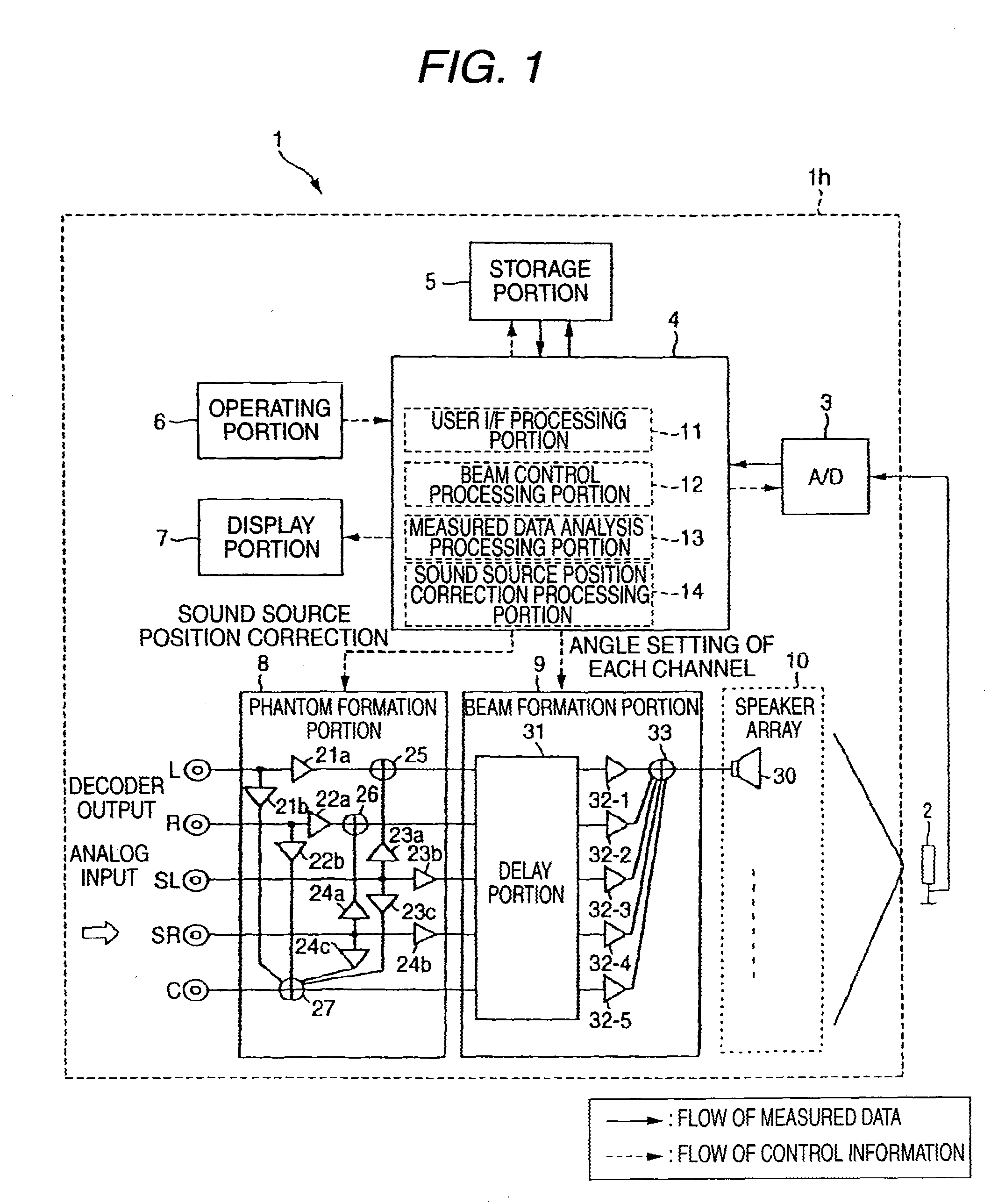
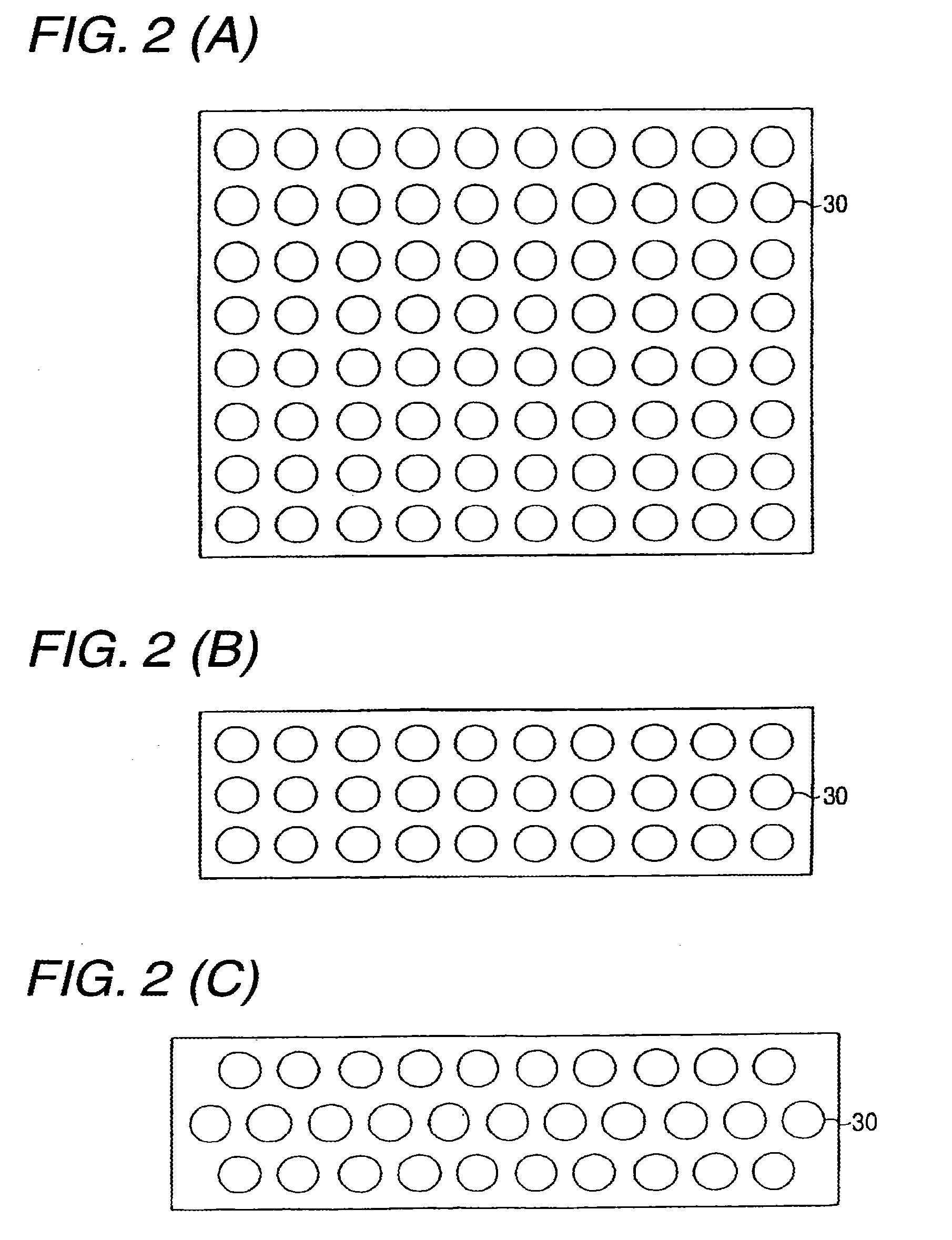
[0069]FIG. 1 is a block diagram showing the schematic configuration of a speaker array apparatus according to an embodiment of the present invention. FIG. 2 are views of layouts of speaker arrays, in which (A) shows the case where speakers are arrayed in a matrix, (B) shows the case where speakers are arrayed in three lines, and (C) shows the case where speakers are arrayed in three lines so that the speakers in the second line are displaced from the speakers in the first line and the speakers in the third line. The following description will be made about an example of a speaker array apparatus serving for a 5.1ch surround-sound system. In the following description, term a front left channel L(Left)ch, a front right channel R(Right)ch, a center channel C(Center)ch, a rear left channel SL(Surround Left)ch, a rear right channel SR(Surround Right)ch, and a subwoofer LFE(Low Frequency Effects)ch in the 5.1ch surround-sound system. In the 5.1ch surround-sound system, an audio signal of ...


PUM


Abstract

To provide a speaker array apparatus and a method for setting audio beams in a speaker array apparatus, in which the degree of freedom in the place where the speaker array apparatus is installed is high, and a user can set audio beams easily. A speaker array apparatus 1 sweeps a range of from 0 degree to 180 degrees in front of a speaker array 10 with audio beams based on an audio signal limited to a band where the angles of the audio beams can be adjusted. The speaker array apparatus 1 collects direct sounds or reflected sounds of the audio beams through a nondirectional microphone 2. The speaker array apparatus 1 analyzes the collected audio data, detects peaks not lower than a threshold value, and checks symmetry among the peaks. When there is a symmetry, the angles where the peaks were detected are set as angles with which audio beams of respective channels of a surround-sound should be output. Thus, outgoing angles of the audio beams can be set in optimum positions in accordance with the shape of a room or the installation position where the speaker array apparatus is installed.

Description

[0001]This is a continuation of U.S. patent application Ser. No. 10 / 597,407 filed 24 Jul. 2006, which is a National Phase filed under 35 U.S.C. §371 of PCT / JP2005 / 011345, filed 21 Jun. 2005, which claims priority to JP 2004-185364, filed 23 Jun. 2004, the entire contents of which are incorporated herein by reference.TECHNICAL FIELD [0002]The present invention relates to a speaker array apparatus for outputting a plurality of audio beams to reproduce a surround-sound, and particularly relates to a speaker array apparatus having a high degree of freedom as to an installation location thereof so that the audio beams can be set easily.BACKGROUND ART [0003]In the background art, there has been a proposed a technique in which a plurality of audio beams are formed by use of a speaker array constituted by a plurality of speakers disposed in a matrix, so that propagation directivities of the audio signals are controlled (for example, see Patent Document 1). By use of this technique, it is no...

Claims


Application Information

Patent Timeline
Patent Type & Authority Applications(United States)
IPC IPC(8): H04R5/00H04R1/40H04S5/02H04S7/00
CPCH04R1/403H04R3/12H04S7/301H04R2203/12H04R2205/022H04R2201/401
Inventor TAKUMAI, SUSUMU
Owner YAMAHA CORP
Why Eureka
Try Eureka