Storage system, control method of storage device

a storage system and control method technology, applied in the field of electronic devices, can solve the problems of increasing power consumption, increasing the size of the device, and increasing the number of the device,

Inactive Publication Date: 2011-01-20
HITACHI LTD
View PDF10 Cites 34 Cited by
  • Summary
  • Abstract
  • Description
  • Claims
  • Application Information

AI Technical Summary

Benefits of technology

[0017]With the storage system according to the present invention, the operational status of a storage device can be controlled using, as reference, whether or not the electric energy consumption of the storage device over a predetermined period exceeds a prescribed upper limit. Consequently, regardless of instantaneous load increases / decreases, the storage device enables necessary services to be provided while keeping the electric energy consumption over a period within a prescribed upper limit.

Problems solved by technology

Accordingly, storage devices have become increasingly larger in scale, resulting in an increase in power consumption.
In addition, there is an upward trend in the number of electronic devices including storage devices to be installed at a data center or the like, and the power consumption by an entire data center is also on the rise.
Meanwhile, as the power consumption of electronic devices increases, the amount of released heat also increases, which in turn causes an increase in the power consumption of cooling facilities at the data centers.

Method used


Image

  • Storage system, control method of storage device
  • Storage system, control method of storage device
  • Storage system, control method of storage device

Examples


first embodiment

[0053]A first embodiment of the present invention will now be described with reference to the drawings.

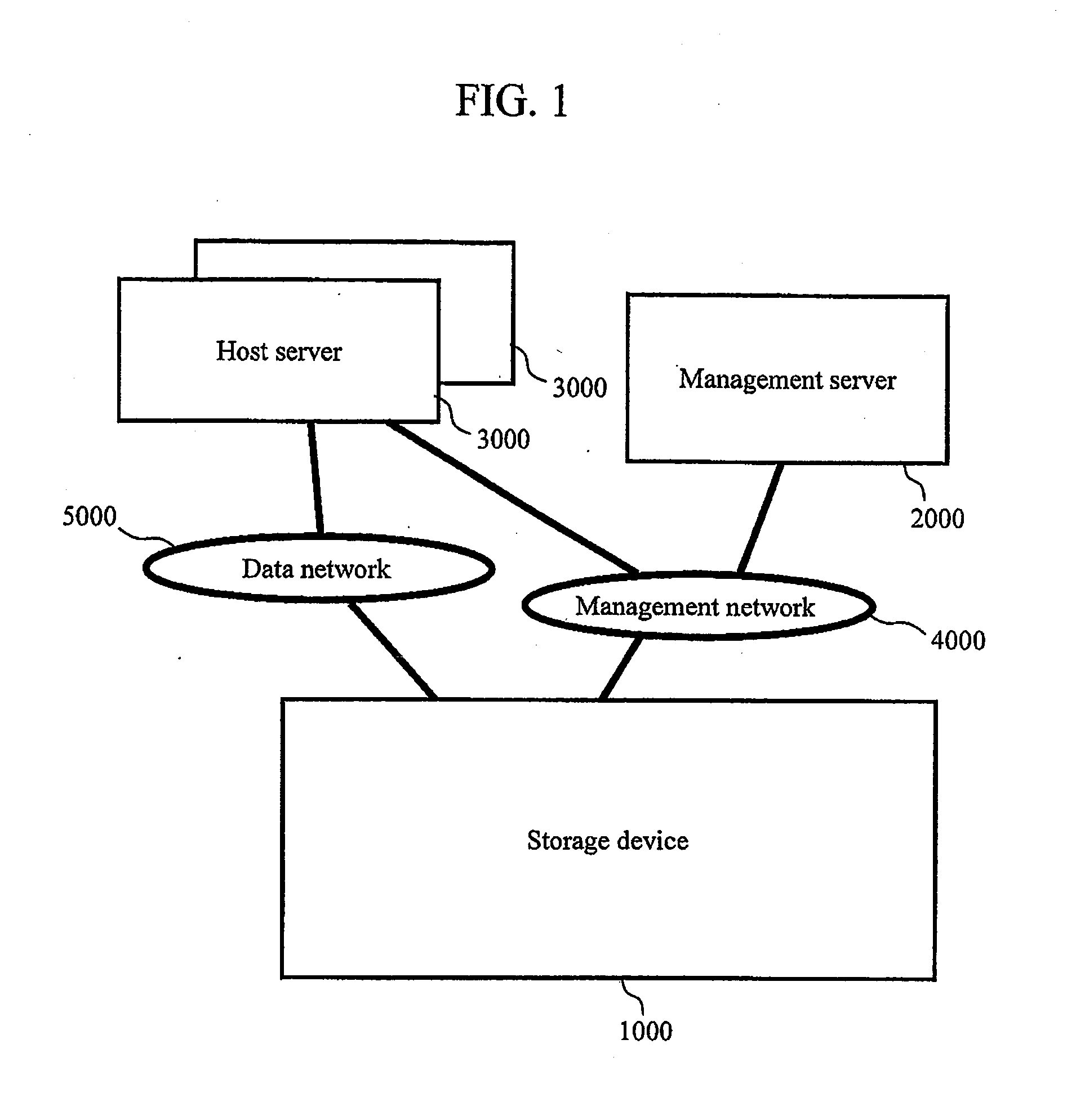
[0054]FIG. 1 is a block configuration diagram of a storage system according to the first embodiment of the present invention. The storage system according to the present first embodiment includes a storage device 1000, a management server 2000, and a host server 3000. There may either be one each or a plurality each of the storage device 1000, the management server 2000 and the host server 3000.

[0055]It is assumed that each device making up the storage system includes a CPU or the like having a timer function, and that the same time is respectively retained by all of the devices. An arbitrary method may be used to synchronize the time of each device. For example, a clock server including a clock function may be prepared on a management network 4000, whereby all the devices may periodically inquire the aforementioned server for the time so as to share the same time. In the following...

second embodiment

[0343]A second embodiment of the present invention considers, in addition to the first embodiment, operations of an application of the host server 3000 which performs data input / output to / from a logical volume associated with the aforementioned power saving control unit of the storage device 1000 when a state transition of the power saving control unit is performed.

[0344]In the present second embodiment, an aforementioned application of the host server 3000 concludes data read / write processing before an RG of the storage device 1000 used by the application enters a power saving state and data read / write processing is disabled. Furthermore, when it is known that the RG will enter a power saving state and the operation of the application will be affected, the host server 3000 notifies, in advance, a service provision schedule of the application to an administrator and a client receiving the service of the application. Specifically, in addition to the configuration described in the fir...

third embodiment

[0420]In a third embodiment of the present invention, a different operation example when creating power limitation information 2114 will be described. Components of the respective devices and other operations are the same as the first and second embodiments.

[0421]FIG. 24 is a diagram showing details of step S2111A7 shown in FIG. 15 according to the present third embodiment. Hereinafter, the respective steps shown in FIG. 24 will be described.

[0422](FIG. 24: Steps S2111B1 to S2111B12)

[0423]These steps are the same as in FIG. 16 described in the first embodiment. However, a step S2111B13 has been newly inserted between steps S2111B11 and S2111B12.

[0424](FIG. 24: Step S2111B13)

[0425]The power management program 2111 judges whether or not the scheduled total excess electric energy 21174 is equal to or lower than 0. If equal to or lower than 0, it is judged that the respective energized parts do not need to be additionally subjected to state transitions and the present operation flow is ...


PUM


Abstract

The present invention provides a technique that enables, in an environment in which an upper limit of electric energy consumption is prescribed for a specific period, operations of a storage device while keeping the electric energy consumption within the prescribed upper limit and, at the same time, maintaining operations of a disk device of a storage device necessary for providing services to a user. A storage system according to the present invention includes a storage device having one or more energized parts and a management device that manages operations of the storage device. The management device acquires electric energy consumption of the energized part and controls the operational state of the energized part so that the electric energy consumption of the storage device over a predetermined period does not exceed a prescribed upper limit.

Description

TECHNICAL FIELD[0001]The present invention relates to electronic devices such as a storage device.BACKGROUND ART[0002]A storage device is managed by a RAID (Redundant Array of Inexpensive Disks) method, and includes a plurality of disk devices arranged in an array and a control unit that controls the plurality of disk devices. A storage device is connected to a host computer such as a server (hereinafter also referred to as a host server), and provides a logical storage area (hereinafter also referred to as a logical volume) arranged so as to be redundant based on a RAID structure.[0003]In recent years, the amount of data to be managed by corporations and the like is increasing on a daily basis. Accordingly, storage devices have become increasingly larger in scale, resulting in an increase in power consumption. In addition, there is an upward trend in the number of electronic devices including storage devices to be installed at a data center or the like, and the power consumption by...

Claims


Application Information

Patent Timeline
Patent Type & Authority Applications(United States)
IPC IPC(8): G06F1/32G06F1/26G06F12/00
CPCG06F3/0625G06F3/0634Y02B60/1246G06F3/0674G06F3/067Y02D10/00
Inventor MORI, HAJIMEOUCHI, KATSUMITAGUCHI, YUICHI
Owner HITACHI LTD
Why Eureka
Try Eureka