Signal amplification apparatus with advanced linearization

a signal amplifier and linearization technology, applied in the direction of amplifier combinations, amplifier modifications to reduce non-linear distortion, amplifiers with field-effect devices, etc., can solve the problems of low power, small rf front end, inter-modulation distortion,

Inactive Publication Date: 2011-01-27
CHUNG ANG UNIV IND ACADEMIC COOP FOUND
View PDF3 Cites 1 Cited by
  • Summary
  • Abstract
  • Description
  • Claims
  • Application Information

AI Technical Summary

Problems solved by technology

The heterodyne method has a limitation in realizing a low cost, low power, and small RF front end.
However, in the direct conversion method, inter-modulation distortion occurs due to non-linearity that occurs in each circuit.
In inter-modulation distortion, undesired frequency components are generated due to non-linear components that are generated by the active element.
Thus, a transceiver for transmitting and receiving RF signals, when the gain of an input signal is high, non-linear components are relatively increased, and distortion of a transmitted signal occurs, and a problem occurs in data transmission.
In these signal linearization methods, many RF elements are used to cause a high cost and high power consumption and the volume of a circuit is increased.
However, the signal linearization method can be used only in a narrow bandwidth and is not appropriate for compensating for linearity of large signals output from a transmission unit.

Method used


Image

  • Signal amplification apparatus with advanced linearization
  • Signal amplification apparatus with advanced linearization
  • Signal amplification apparatus with advanced linearization

Examples


Embodiment Construction

[0030]Hereinafter, the present invention will be described in detail by explaining exemplary embodiments of the invention with reference to the attached drawings.

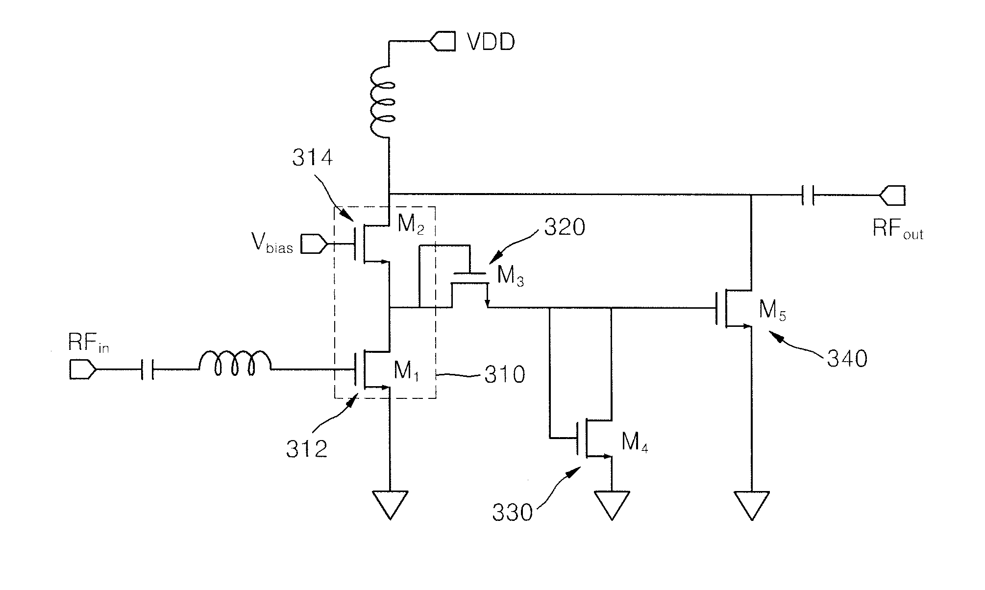
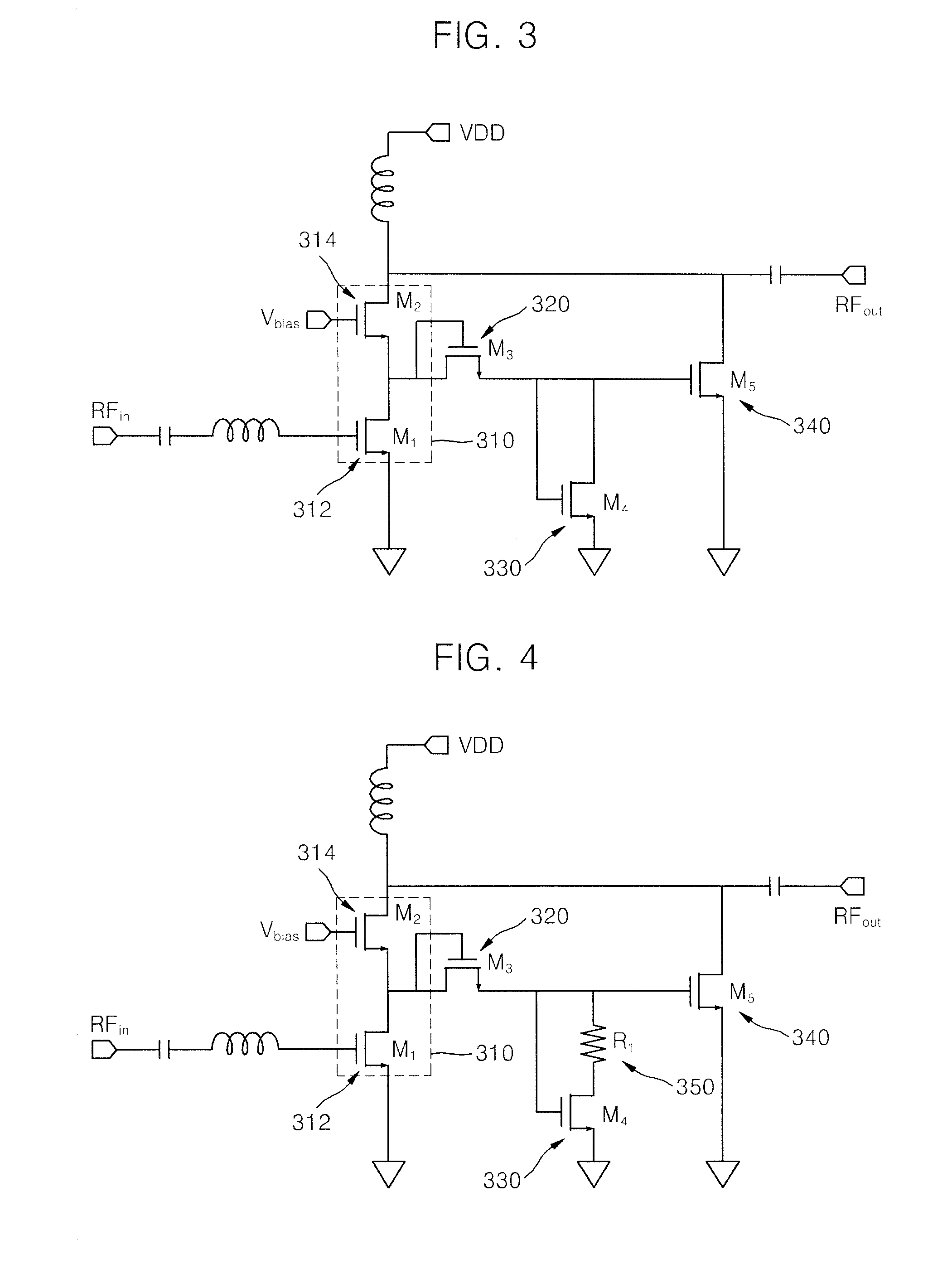
[0031]FIG. 3 is a circuit diagram of a signal amplification apparatus with advanced linearization according to an embodiment of the present invention. Referring to FIG. 3, the signal amplification apparatus with advanced linearization according to the present embodiment includes a plurality of active elements, i.e., a driving unit 310 including a first active element 312 and a second active element 314, a third active element 320, a fourth active element 330, and a fifth active element 340.

[0032]In the signal amplification apparatus of FIG. 3, the active elements, the first active element 312 through the fifth active element 340, are MOSFETs. However, these MOSFETs as active elements can be replaced by other three-terminal semiconductor devices that are commonly used.

[0033]The driving unit 310 has the same configuration as ...


PUM


Abstract

Provided is a signal amplification apparatus with advanced linearization, the signal amplification apparatus including: a driving unit having a structure of a cascode amplifier including a first active element and a second active element and outputting an amplification signal in which an input signal is amplified, to an output terminal; a third active element receiving a signal diverged between the first active element and the second active element while gate and drain terminals of the third active element are shorted; a fourth active element of which gate and drain terminals are connected to a source terminal of the third active element; and a fifth active element of which gate terminal is connected to the drain terminal of the fourth active element, outputting a non-linear signal having an opposite phase to the amplification signal to the output terminal so as to cancel a third-order inter-modulation distortion component included in the input signal. An amplification signal in which an input signal is amplified is combined with a non-linear signal having an opposite phase to the amplification signal and a low gain and is output so that a third-order inter-modulation distortion component included in the input signal can be cancelled and a signal with advanced linearity can be output.

Description

CROSS-REFERENCE TO RELATED PATENT APPLICATION[0001]This application claims the benefit of Korean Patent Application No. 10-2009-0066467, filed on Jul. 21, 2009, in the Korean Intellectual Property Office, the disclosure of which is incorporated herein in its entirety by reference.BACKGROUND OF THE INVENTION[0002]1. Field of the Invention[0003]The present invention relates to a signal amplification apparatus with advanced linearization, and more particularly, to an apparatus for removing distortion signals generated due to non-linearization of an active element when an input signal is amplified and output.[0004]2. Description of the Related Art[0005]In general, mobile communication systems require an apparatus for transmitting and receiving signals. When signals are transmitted from a transmission terminal to a receiving terminal, a loss occurs due to characteristics of a channel according to a transmission distance. Thus, in order to compensate for the loss, mobile communication sys...

Claims


Application Information

Patent Timeline
Patent Type & Authority Applications(United States)
IPC IPC(8): H03F3/16
CPCH03F1/223H03F1/3205H03F2200/451H03F2200/181H03F2200/108H03F1/22H03F1/32
Inventor CHOI, YOUNG-WANKIM, DO-GYUNHONG, NAM-PYO
Owner CHUNG ANG UNIV IND ACADEMIC COOP FOUND
Why Eureka
Try Eureka