Method of manufacturing oscillator device, and optical deflector and optical instrument with oscillator device based on it

a technology of oscillator and manufacturing method, which is applied in the direction of manufacturing tools, instruments, optical elements, etc., can solve the problems of dispersion of the resonance frequency of the oscillator, dispersion of the spring constant and the inertia moment of the oscillator, and finishing errors in the oscillator, etc., to achieve high precision, fast adjustment, and long time

Inactive Publication Date: 2011-01-27
CANON KK
View PDF13 Cites 7 Cited by
  • Summary
  • Abstract
  • Description
  • Claims
  • Application Information

AI Technical Summary

Benefits of technology

0010] Furthermore, although the resonance frequency may be slowly adjusted to a target frequency by, for example, alternately repeating the removal of the inertia moment of the oscillator and the measurement of the resonance frequency, in this approach the adjustment of the resonance frequency of the oscillator dev...

Problems solved by technology

By the way, in the manufacturing process of an oscillator and a torsion spring which constitute the oscillator device, an error may occur when a wafer is processed, causing dispersion of the spring constant and the inertia moment of the oscillator device.
Here, since the resonance frequency of the oscillator device is determined by the inertia moment of the oscillator and the spring constant of the torsion spring, a finishing error in the manufacturing process such as described above will cause dispersion of the res...

Method used


Image

  • Method of manufacturing oscillator device, and optical deflector and optical instrument with oscillator device based on it
  • Method of manufacturing oscillator device, and optical deflector and optical instrument with oscillator device based on it
  • Method of manufacturing oscillator device, and optical deflector and optical instrument with oscillator device based on it

Examples


embodiment 1

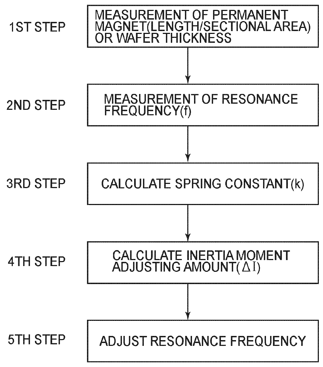
[0038] In the first embodiment, the present invention is applied to a method of manufacturing an oscillator device including an oscillator which is supported relative to a fixed member by a torsion spring for oscillation (torsional oscillation) around a torsion axis and is arranged to be driven at a resonance frequency.

[0039] FIG. 1 is a flow chart for explaining the oscillator device manufacturing method of the present embodiment.

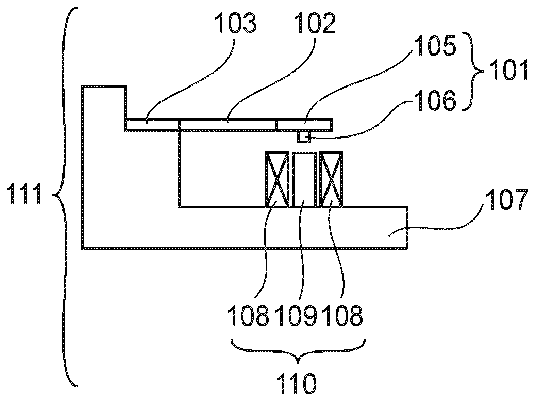
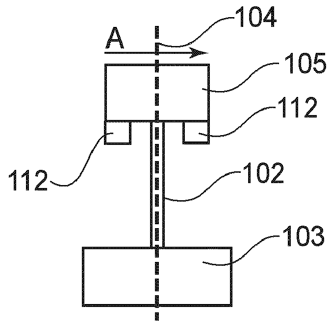
[0040] FIGS. 2A and 2B are diagrams for explaining the oscillator device manufacturing method of the present embodiment, wherein FIG. 2A is a front elevation of an oscillator device of the present embodiment, and FIG. 2B is a sectional view along a plane passing through a torsion axis 104 and being perpendicular to sheet of the drawing.

[0041] In FIGS. 2A and 2B, denoted at 101 is an oscillator, and denoted at 102 is a torsion spring. Dented at 103 is a fixed member, and denoted at 104 is a torsion axis. Denoted at 105 is a silicon member, and denoted at 10...

embodiment 2

[0084] The second embodiment will be described with reference to an oscillator device manufacturing method which differs from the first embodiment.

[0085] FIGS. 4A and 4B are diagrams for explaining the oscillator device manufacturing method of the present embodiment. FIG. 4A is a front elevation of the oscillator device of the present embodiment, and FIG. 4B is a sectional view along a plane passing through a torsion axis 410 and being perpendicular to sheet of the drawing.

[0086] In FIGS. 4A and 4B, denoted at 401 is a first oscillator, and denoted at 402 is a second oscillator. Denoted at 403 is a first torsion spring, and denoted at 404 is a second torsion spring. Denoted at 405 is a first silicon member.

[0087] Denoted at 406 is a first protrusion, and denoted at 407 is a second silicon member. Denoted at 408 is a second protrusion, and denoted at 409 a fixed member. Dented at 410 is a torsion axis.

[0088] Denoted at 411 is a permanent magnet, and denoted at 412 is a fixed base. De...

embodiment 3

[0113] The third embodiment will be described with reference to an oscillator device manufacturing method which differs from the preceding embodiments.

[0114] FIGS. 6A-6C are diagrams for explaining the oscillator device manufacturing method of the present embodiment. FIG. 6A is a front elevation of the oscillator device of the present embodiment, and FIG. 6B is a diagram of the oscillator device of FIG. 6A as seen from the opposite side. FIG. 6C is a sectional view taken along a plane passing through a torsion axis 608 and perpendicular to the sheet of the drawing.

[0115] Furthermore, FIG. 7 is a flow chart for explaining the oscillator device manufacturing method of the present embodiment.

[0116] Denoted in FIG. 6 at 601 is an oscillator, and denoted at 602 is a torsion spring. Denoted at 603 is a fixed member, and denoted at 604 is a reflector board. Denoted at 605 is a joining board, and denoted at 606 is a permanent magnet. Denoted at 607 is a silicon member, and denoted at 608 is...


PUM

PropertyMeasurementUnit
Weightaaaaaaaaaa
Frequencyaaaaaaaaaa
Photosensitivityaaaaaaaaaa

Abstract

A method of manufacturing an oscillator device having an oscillator supported relative to a fixed member by a torsion spring for oscillation around a torsion axis and arranged to be driven at a resonance frequency, which method includes a first step for determining an assumed value of an inertia moment weight of the oscillator, a second step for measuring the resonance frequency, a third step for calculating a spring constant of the torsion spring, from the assumed value of the inertia moment weight and the measured resonance frequency obtained at said first and second steps, a fourth step for calculating an adjustment amount for the inertia moment of the oscillator or for the spring constant of the torsion spring, based on the spring constant calculated at said third step and a target resonance frequency determined with respect to the resonance frequency of the oscillator, so as to adjust the resonance frequency to the target resonance frequency, and a fifth step for adjusting the resonance frequency of the oscillator to the target resonance frequency based on the calculated adjustment amount.

Description

TECHNICAL FIELD[0001] This invention relates to a method of manufacturing an oscillator device, and an optical deflector and optical instrument comprised of an oscillator device manufactured by the manufacturing method. More specifically, the invention concerns a technique which enables an oscillator device suitably usable in various optical instruments including, for example, a projection display for projecting an image based on the scanning deflection of light, and an image forming apparatus such as a laser beam printer, a digital copying machine and so on having an electrophotographic process.BACKGROUND ART[0002] In recent years, various proposals have been made with regard to optical scanning systems (and optical scanning devices) arranged as an optical deflector to perform sinusoidal vibration based on a resonance phenomenon.[0003] In the optical deflectors using such resonance phenomenon, there is a certain resonance frequency determined as a targeted frequency of eigenmode re...

Claims


Application Information

Patent Timeline
IPC IPC(8): G02B26/08B23Q17/00
CPCG02B26/085Y10T29/49774H04N1/1135G02B26/105
Inventor MIYAGAWA, SUGURUAKIYAMA, TAKAHIROTORASHIMA, KAZUTOSHIKATO, TAKAHISAFUJII, KAZUNARI
Owner CANON KK
Why Eureka
Try Eureka