Visualization of product build using precedence transversal method

a product build and precedence transversal technology, applied in the field of information technology, can solve the problems of inability to analyze the assembly sequence of complex assemblies of previous process planning systems, and inability to accurately represent a selected process

Inactive Publication Date: 2011-01-27
THE BOEING CO
View PDF21 Cites 39 Cited by
  • Summary
  • Abstract
  • Description
  • Claims
  • Application Information

AI Technical Summary

Benefits of technology

In some embodiments, the method for visualization of product build may include formulating a plurality of installation plans each having processes, components and resources adapted to direct production of a portion of a structure within a build sequence of the structure; formulating a control station precedence network by arranging the installation plans according to precedence within the build sequence of the structure; enabling three-dimensional virtual visualization of a temporal build state of the portion of a structure for each of the installation plans; determining a minimum manufacturing context of the components and resources in the installation plans; and determining a maximum manufacturing context of the components and resources in the installation plans.

Problems solved by technology

Although existing process planning and analysis methods are useful, they nevertheless exhibit several drawbacks, and thus may not accurately represent a selected process.
Since existing methods generally do not permit variability in tasks or resources in the process to be effectively resolved, conflicts that arise during the product assembly must often be resolved informally on the factory floor, which in turn, often requires expensive and time-consuming rework.
Previous process planning systems may not be capable of analyzing the assembly sequence of complex assemblies in a sufficiently discreet manner to identify problems prior to production implementation.
When multiple sub-products or product systems (e.g. hydraulics, fuel, electrical, structures, etc.) are planned by separate technical groups, there may be no efficient method of determining if dependent parts are installed in a sequence which supports specific assembly sequence requirements (i.e., sequencing anomalies).
This inability to analyze and correct assembly problems prior to production implementation may cause assembly sequence conflicts to not be identified until physical assembly on the factory floor.
This may cause change, error and rework which may affect cost and schedule.
Current process planning methods may be labor intensive and prone to error.
This method may not allow the product to be visualized in a three-dimensional space and may be dependent on human interpretation of processes to identify the temporal assembly configuration.
This method may not represent the temporal assembly state of a product but may only validate that the product design is complete.
However, this method may be difficult to maintain for multiple product configurations and may not accurately represent the process input from multiple disciplines.

Method used


Image

  • Visualization of product build using precedence transversal method
  • Visualization of product build using precedence transversal method
  • Visualization of product build using precedence transversal method

Examples


Embodiment Construction

The present invention relates to systems and methods for production planning in a manufacturing process. Many specific details of certain embodiments of the invention are set forth in the following description and in FIGS. 1 through 5 to provide a thorough understanding of such embodiments. One skilled in the art, however, will understand that the present invention may have additional embodiments, or that the present invention may be practiced without several of the details described in the following description.

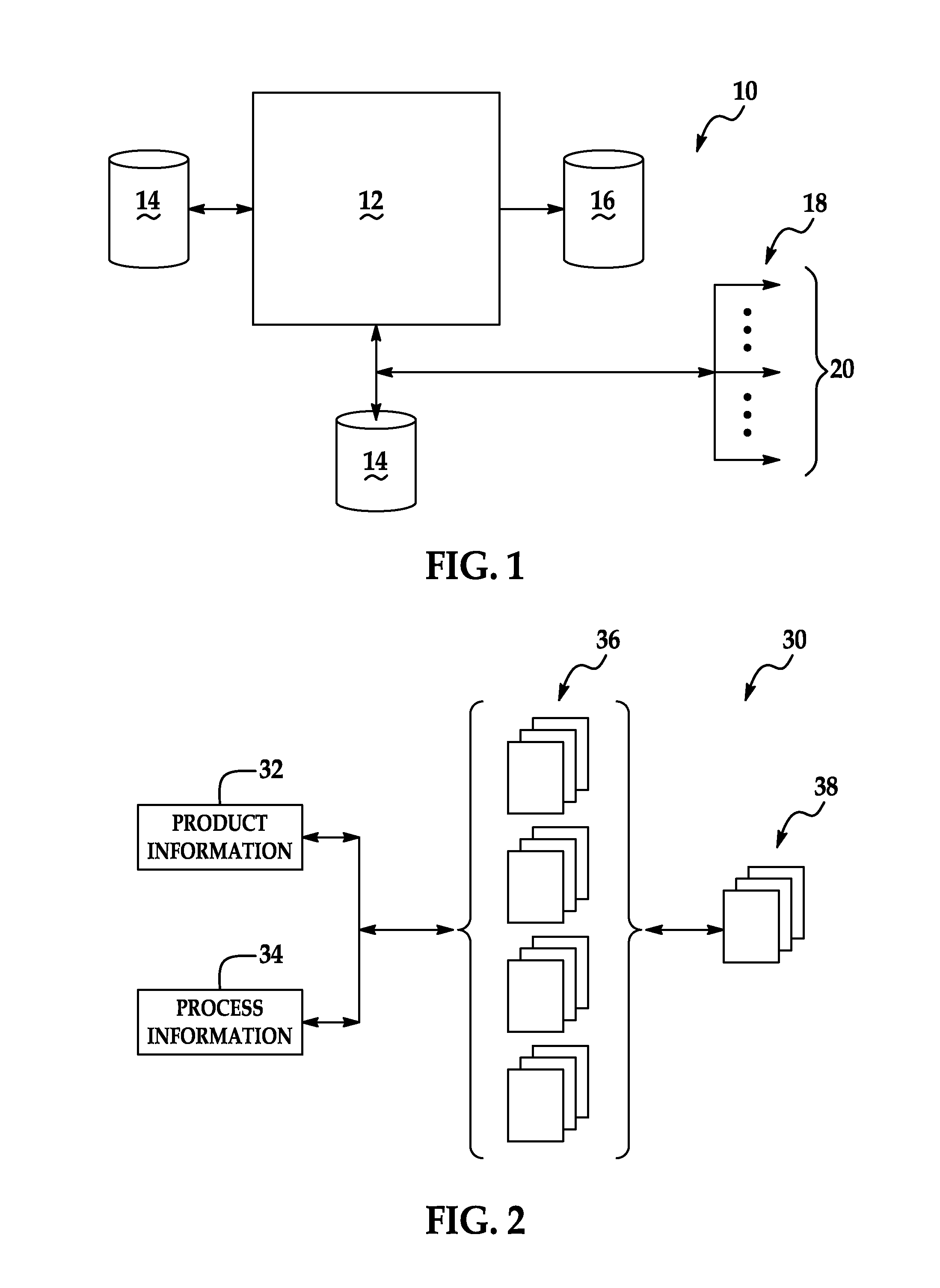
FIG. 1 is a block diagrammatic view of an apparatus 10 for production planning in a manufacturing process, according to an embodiment of the invention. The apparatus 10 includes a processing unit 12 that generally includes any programmable electronic device that is operable to receive programming instructions and input data, and to process the data according to the programming instructions. Although a single processing unit is shown in FIG. 1, the processing unit 12 may be c...


PUM


Abstract

A method for visualization of product build which includes compilation of a virtual temporal configuration of an in-process assembly and visualization of the results using three-dimensional representations of the affected products and associated resources. An illustrative embodiment of the method includes formulating a plurality of installation plans each adapted to direct production of a portion of a product within a build sequence of the product and enabling three-dimensional virtual visualization of a temporal build state of the portion of a product for each of the installation plans.

Description

TECHNICAL FIELDThe disclosure generally relates to information technology pertaining to planning and assembly of complex structures such as aircraft. More particularly, the disclosure relates to visualization of product build using a precedence transversal method which includes compilation of a virtual temporal configuration of an in-process assembly and visualization of the results using three-dimensional representations of the affected products and associated resources.BACKGROUND OF THE INVENTIONComplex manufacturing projects such as the design and manufacture of aircraft generally require that engineering information, component parts and processes be successfully integrated. With regard in particular to the production of aircraft, typically hundreds of thousands of parts and associated processes must be successfully integrated according to a comprehensive plan to produce an aircraft in accordance with the engineering information.Engineering information typically includes engineer...

Claims


Application Information

Patent Timeline
Patent Type & Authority Applications(United States)
IPC IPC(8): G06F19/00
CPCG05B19/41805G05B2219/31029G05B2219/32084G05B2219/31053G05B2219/31044Y02P90/02
Inventor BOUFFIOU, CARL E.SCHREIBER, ROBERT J.FRANZEN, STEVEN E.ANELLE, JOEKEHNER, WILLIAM A.VANHORNE, MARK E.LORBESKI, ROBERT
Owner THE BOEING CO
Why Eureka
Try Eureka