Solar energy collection system

a solar energy collection and solar energy technology, applied in the field of solar energy collection systems, can solve the problems of manufacturing, installation and repair of the cpv system, and the most expensive component of the photovoltaic solar collection system,

Active Publication Date: 2011-02-03
SKYLINE SOLAR INC +1
View PDF54 Cites 100 Cited by
  • Summary
  • Abstract
  • Description
  • Claims
  • Application Information

AI Technical Summary

Benefits of technology

[0005]In one aspect of the present invention, a solar energy collection system that includes multiple longitudinally adjacent collectors is described. The collectors are coupled end to end to form a collector row. The collector row extends along a longitudinal axis and is arranged to rotate about a pivot axis to track the sun in at least one dimension. Each collector includes a reflector, one or more solar receivers and a support structure. The support structure includes a tube assembly that underlies the reflector. The tube assemblies of the collector row are arranged end to end along the longitudinal axis. There is a space between the tube assemblies of adjacent collectors in the collector row, where the reflectors of the adjacent collectors extend beyond the underlying tube assemblies to form a substantially continuous reflective surface over the space. A coupling device is positioned in the space between the tube assemblies. The coupling device connects and helps to rotate the tube assemblies of the adjacent collectors.
[0006]In some implementations, the gap between adjacent reflectors is minimal e.g., less than approximately 10 or 15 millimeters. A minimal gap helps the adjacent reflectors cooperate to form a substantially continuous flux line on the receivers of the associated collectors. In some designs, the gap is covered at least in part by a reflective splice that helps further reduce or eliminate discontinuity in the flux line.

Problems solved by technology

Typically, the most expensive component of a photovoltaic (PV) solar collection system is the photovoltaic cell.
One of the design challenges for any CPV system is the need to balance multiple priorities.
Another consideration is the cost of manufacturing, installing and repairing the CPV system.

Method used


Image

  • Solar energy collection system
  • Solar energy collection system
  • Solar energy collection system

Examples


Embodiment Construction

[0020]The present invention relates generally to solar energy collection. Some aspects of the invention relate to solar collectors, arrangements of multiple solar collectors, and devices for tracking the sun. It should be appreciated that additional embodiments, features and drawings related to the present application are described in Provisional Application No. 61 / 229,905, filed Jul. 30, 2009, entitled “Manufacturable Dual Trough Solar Collector,” which is incorporated herein in its entirety for all purposes.

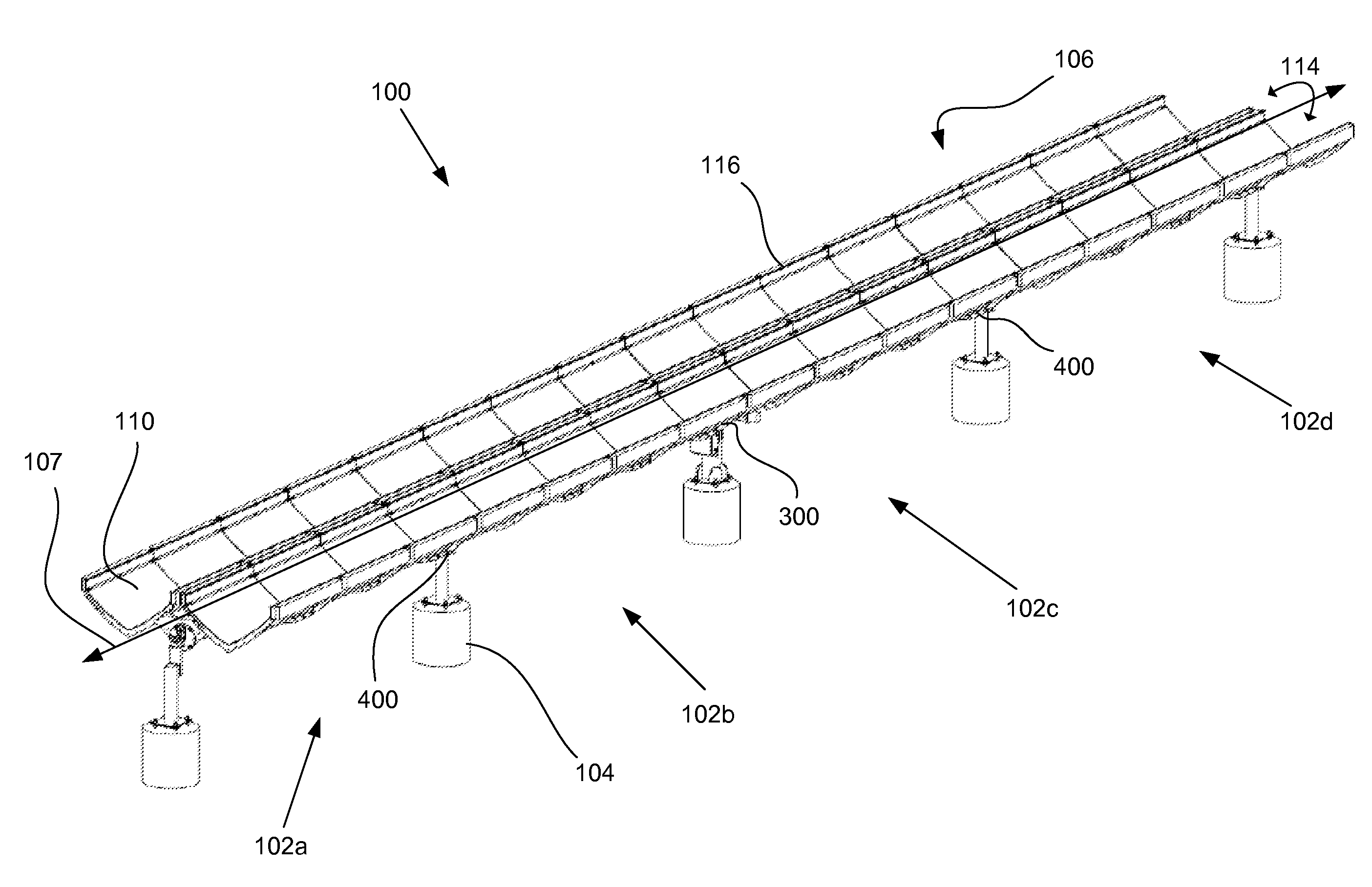
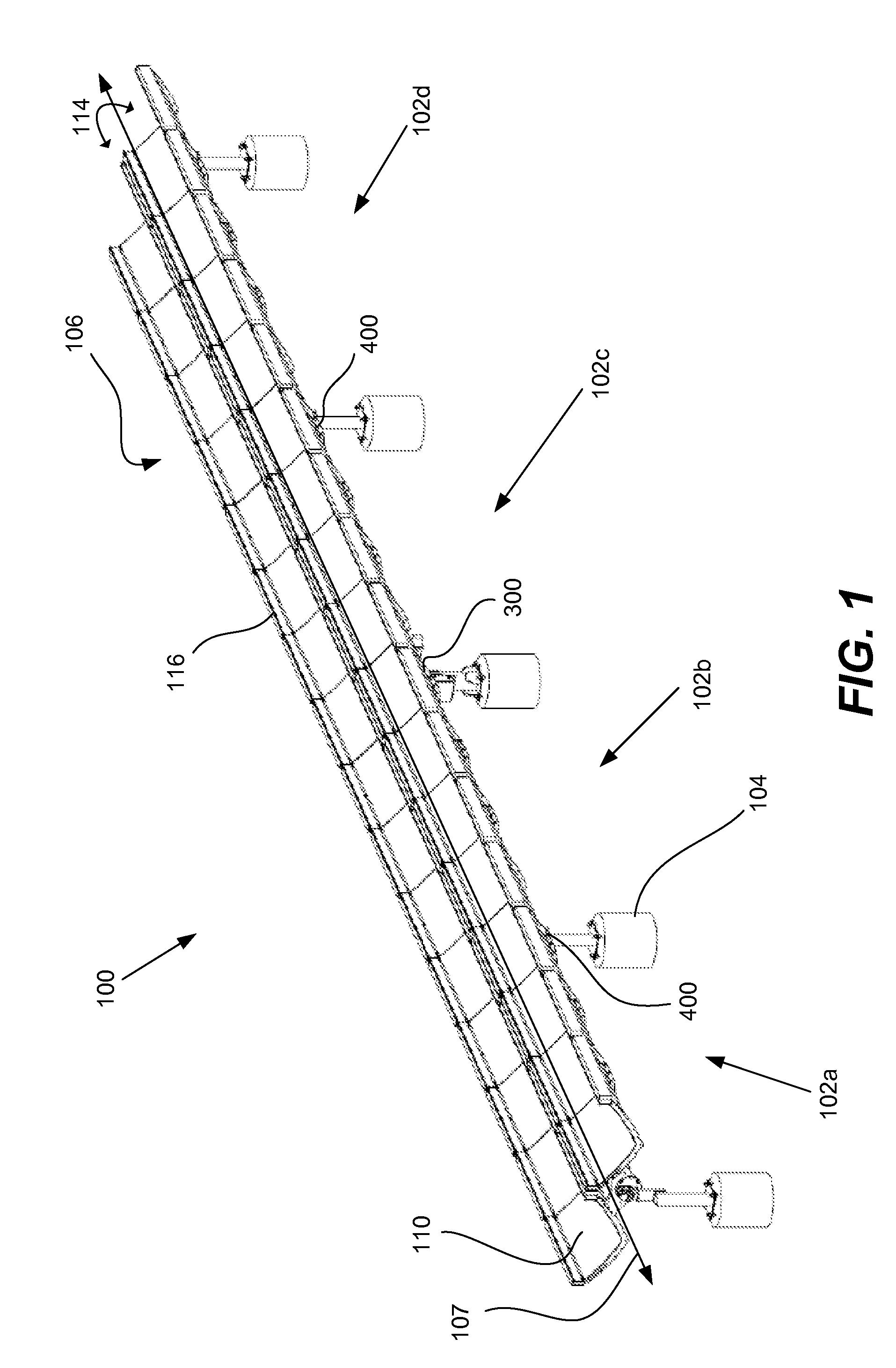
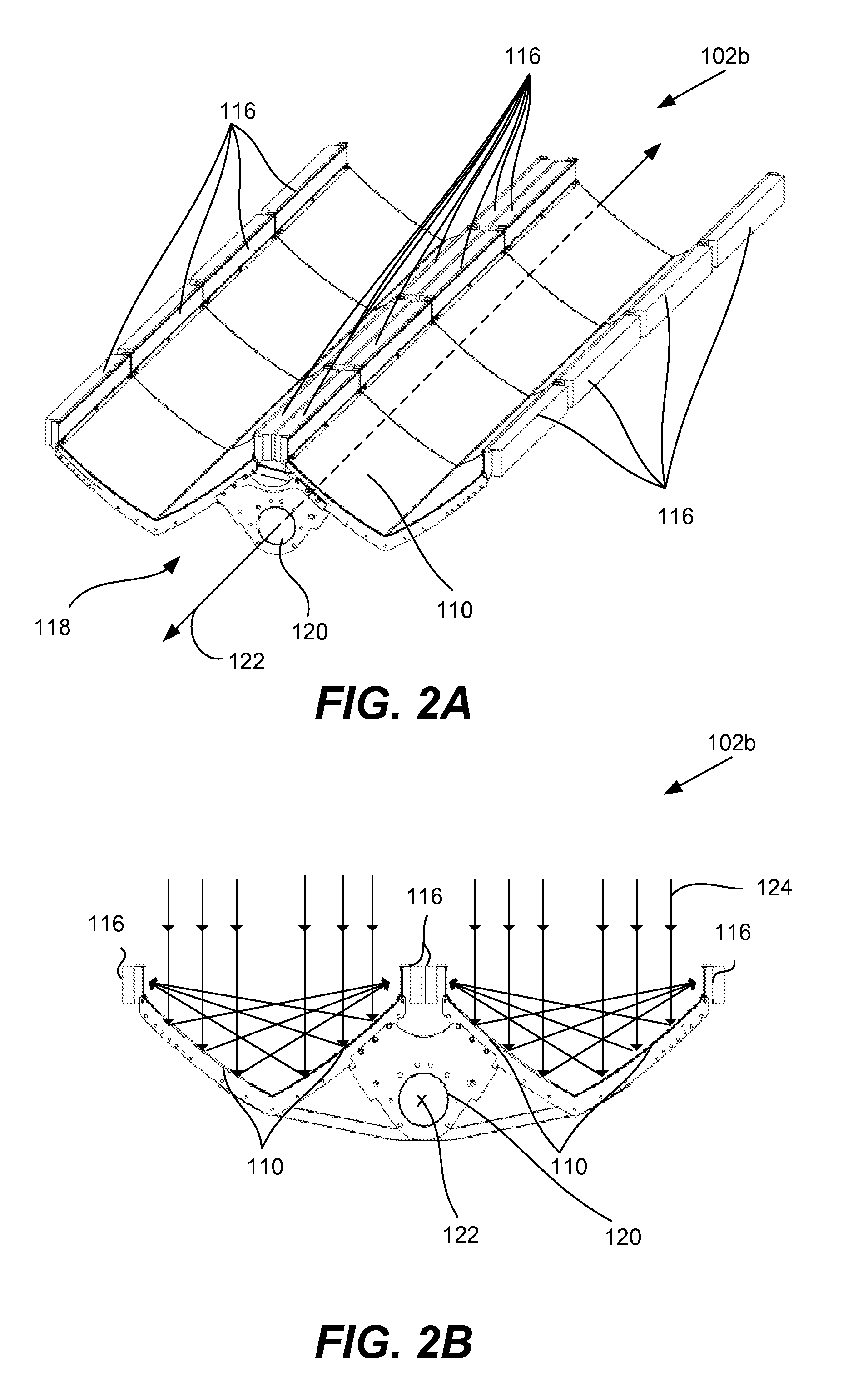
[0021]Referring now to FIG. 1, a solar energy collection system 100 according to one embodiment of the present invention will be described. Solar energy collection system 100 includes multiple solar collectors 102a-102d that are coupled end to end along a longitudinal axis 107 to form a solar collector row 106. Each solar collector includes a reflector 110 that is arranged to direct incident sunlight towards the solar receivers 116. The solar energy collection system 100 is arr...


PUM


Abstract

In one aspect of the present invention, a solar energy collection system that includes multiple longitudinally adjacent collectors is described. The collectors are coupled end to end to form a collector row. The collector row extends along a longitudinal axis and is arranged to rotate about a pivot axis to track the sun in at least one dimension. Each collector includes a reflector, one or more solar receivers and a support structure. The support structure includes a tube assembly that underlies the reflector. The tube assemblies of the collector row are arranged end to end along the longitudinal axis. There is a space between the tube assemblies of adjacent collectors in the collector row, where the reflectors of the adjacent collectors extend beyond the underlying tube assemblies to form a substantially continuous reflective surface over the space. A coupling device is positioned in the space between the tube assemblies. The coupling device connects and helps to rotate the tube assemblies of the adjacent collectors. Some embodiments relate to various types of coupling devices and collector arrangements.

Description

CROSS-REFERENCE TO RELATED APPLICATIONS[0001]This application claims priority to Provisional Patent Application No. 61 / 229,905, filed Jul. 30, 2009, entitled “Manufacturable Dual Trough Solar Collector,” and Provisional Patent Application No. 61 / 362,591, entitled “Optimized Solar Collector,” filed on Jul. 8, 2010, which are incorporated herein in their entirety for all purposes.FIELD OF THE INVENTION[0002]Generally, the present invention relates generally to solar energy collection systems. More specifically, the present application relates to solar collectors and solar collector arrangements for use in concentrating photovoltaic systems.BACKGROUND OF THE INVENTION[0003]Typically, the most expensive component of a photovoltaic (PV) solar collection system is the photovoltaic cell. To help conserve photovoltaic material, concentrating photovoltaic (CPV) systems use minors or lenses to concentrate solar radiation on a smaller cell area. Since the material used to make the optical conc...

Claims


Application Information

Patent Timeline
Patent Type & Authority Applications(United States)
IPC IPC(8): H01L31/052F24S23/70F24S23/71F24S50/20
CPCF24J2/0494F24J2/07F24J2/1047F24J2/523F24J2/525H01L31/0547Y02E10/41Y02E10/44Y02E10/47Y02E10/52H02S20/00F24J2/541F24S20/20F24S23/80F24S25/10F24S25/617F24S30/425F24S70/65H02S20/32H02S40/22Y02E10/40
Inventor DO, KHIEM B.LANGWORTHY, KEVIN R.GABBIANELLI, GIANFRANCOJOHNSON, ERIC C.JULIAN, DOMINICO P.FINOT, MARC A.WYLIE, CAMERON G.
Owner SKYLINE SOLAR INC
Why Eureka
Try Eureka