Machine tool including affected layer detection sensor

a technology of detecting sensor and machine tool, which is applied in the direction of manufacturing tools, mechanical measuring arrangements, instruments, etc., can solve the problems of distal end wear of the sensor, and achieve the effect of avoiding distal end wear

Active Publication Date: 2015-10-08
JTEKT CORP
View PDF15 Cites 5 Cited by
  • Summary
  • Abstract
  • Description
  • Claims
  • Application Information

AI Technical Summary

Benefits of technology

[0007]It is an object of the present invention to provide a machine tool including a non-contact affected layer detection sensor capable of precisely detecting an affected layer and avoiding wear of the distal end of the sensor.

Problems solved by technology

Since the affected layer detection sensor contacts the workpiece, the distal end of the sensor may be worn.

Method used


Image

  • Machine tool including affected layer detection sensor
  • Machine tool including affected layer detection sensor
  • Machine tool including affected layer detection sensor

Examples


Embodiment Construction

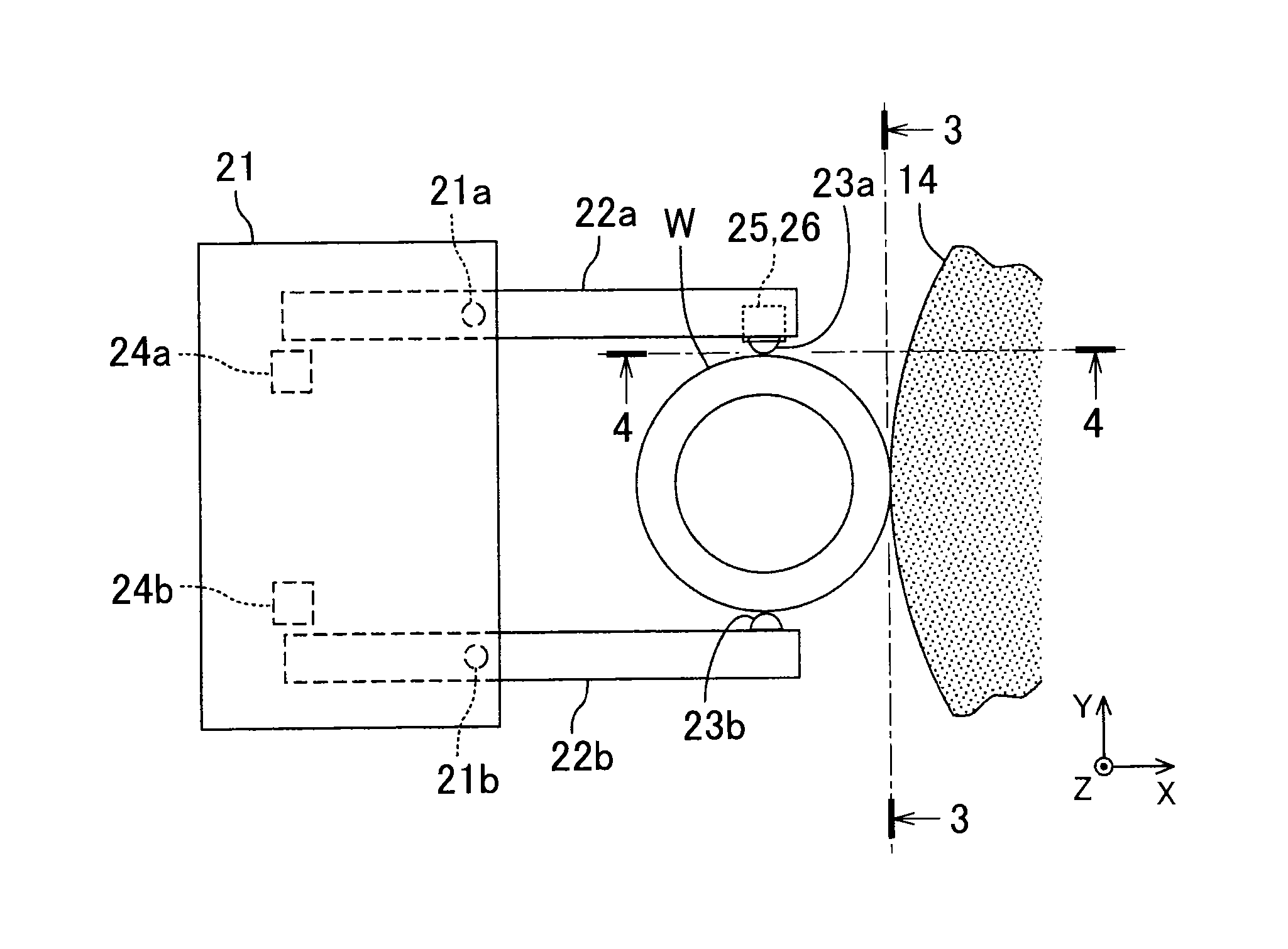
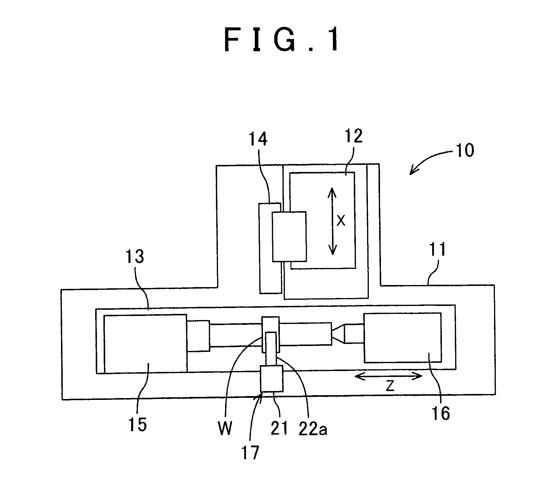
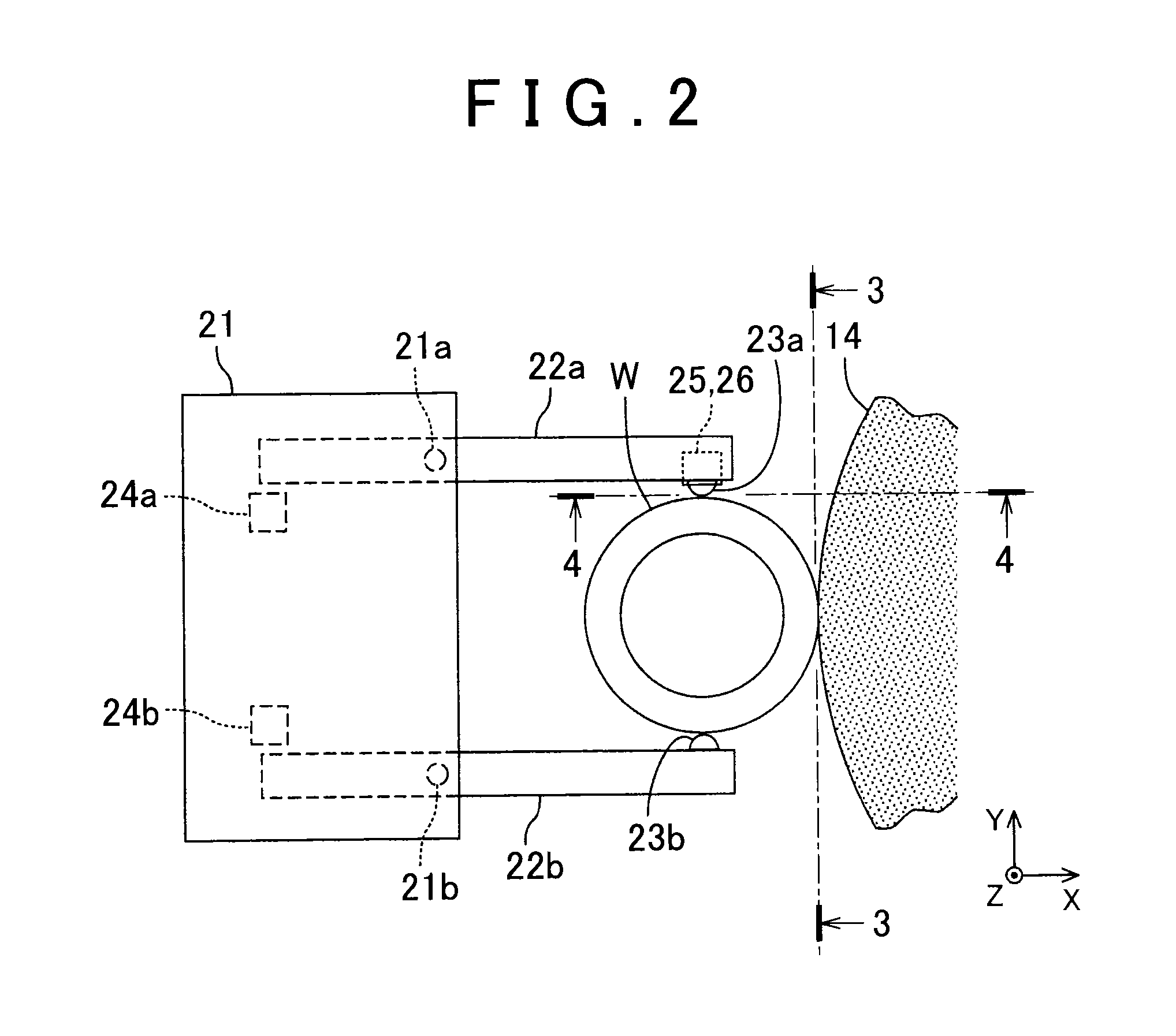
[0022]The configuration of a machine tool according to an embodiment of the present invention will be described with reference to FIG. 1. A cylindrical grinding machine 10 that grinds the outer periphery of a cylindrical workpiece W while rotationally driving the workpiece W is taken as an example of the machine tool according to the embodiment. The cylindrical grinding machine 10 includes a bed 11, a wheel spindle stock 12, a table 13, a grinding wheel 14, a main spindle 15, a tailstock 16, and a measurement unit 17.

[0023]The wheel spindle stock 12 is provided on the bed 11 so as to be reciprocally movable in the X-axis direction. The table 13 is provided on the bed 11 so as to be reciprocally movable in the Z-axis direction that is orthogonal to the X-axis direction. The grinding wheel 14 is provided on the wheel spindle stock 12, supported so as to be rotatable about an axis that extends in parallel with the Z axis, and rotationally driven by a wheel spindle rotating motor (not i...


PUM


Abstract

A machine tool including a non-contact affected layer detection sensor capable of detecting an affected layer with high precision is provided. A machine tool includes a non-contact affected layer detection sensor, a main body, probes and that contact the surface of an workpiece, arm portions supported by the main body, and dimension measurement sensors that output a signal that corresponds to the dimension of the workpiece on the basis of displacement of the arm portions with respect to the main body. The affected layer detection sensor is provided in the arm portion, and outputs a signal that corresponds to an affected state of the workpiece. The arm portions hold the probes respectively, and are displaceable with respect to the main body in accordance with the dimension of the workpiece.

Description

INCORPORATION BY REFERENCE[0001]The disclosure of Japanese Patent Application No. 2014-078432 filed on Apr. 7, 2014 including the specification, drawings and abstract, is incorporated herein by reference in its entirety.BACKGROUND OF THE INVENTION[0002]1. Field of the Invention[0003]The present invention relates to a machine tool including an affected layer detection sensor.[0004]2. Description of the Related Art[0005]Examples of a machine tool including an affected layer detection sensor according to the related art are described in Japanese Patent Application Publication No. 2011-245592 (JP 2011-245592 A), Japanese Patent Application Publication No. 2010-184343 (JP 2010-184343 A), Japanese Patent Application Publication No. 2011-13147 (JP 2011-13147 A), and Japanese Patent Application Publication No. 2011-252877 (JP 2011-252877 A). In JP 2011-245592 A, a wheel spindle stock is provided with an affected layer detection sensor. The affected layer detection sensor described in such d...

Claims


Application Information

Patent Timeline
Patent Type & Authority Applications(United States)
IPC IPC(8): G01B5/016B23Q17/20
CPCB23Q17/20G01B5/016B24B49/02B24B49/105G01N27/90B24B5/04B23Q17/248
Inventor ITO, RYOMUKAIDE, NAOMASA
Owner JTEKT CORP
Why Eureka
Try Eureka