Method for minimizing the gap between a rotor and a housing

a technology of rotor blade and housing, which is applied in the direction of liquid fuel engines, machines/engines, mechanical equipment, etc., can solve the problems of low efficiency, high equipment cost, and inability to meet the needs of maintenance, and achieve the effect of simple means, increased power output, and consequently maximized turbine efficiency

Inactive Publication Date: 2015-06-04
SIEMENS AG
View PDF19 Cites 5 Cited by
  • Summary
  • Abstract
  • Description
  • Claims
  • Application Information

AI Technical Summary

Benefits of technology

[0009]It is therefore an object of the invention to disclose a method by means of which the gap between rotor and housing is minimized in a simple manner at low equipment cost.
[0011]The invention is based in this case on the consideration that a particularly simple monitoring of the gap size would be possible by means of sensors which are as non-invasive as possible and are to be attached in the outer regions. A simple signal, which is generated in the event of contact of rotor and housing, is the sound which is propagated, moreover, by solid bodies, such as a turbine housing. As a result, an acoustic detection of vibrations, which are generated by blade tips colliding with the housing, is enabled in the outer regions of the housing. Therefore, a structure-borne sound monitoring system allows a particularly simple and technically inexpensive checking of a possible contact of blade tips and housing during a displacement of housing and rotor in relation to each other. This enables an accurate setting of a minimum gap.
[0014]In an advantageous embodiment, the rotor can be displaced in an axial direction in relation to the housing for adjusting the size of the gap. Owing to the typically conical shape of the turbine, a uniform reduction of the gap over the entire circumference and in each turbine stage is achieved as a result.
[0017]It is also an object of the invention to disclose a turbine in which the gap between rotor and housing is minimal. This is to be carried out at low equipment cost.
[0020]In an advantageous embodiment, the rotor, particularly at the tips of the rotor blades, can be at least partially abradable. That is to say that corresponding abrasion points are provided and are designed for a slight contact of the housing during the adjustment process. At the abrasion points, material is then possibly worn away, but these points are designed so that no structural damage to the rotor, especially to the rotor blades, occurs as a result. Therefore, the rotor can displaced without risk up to the point of the slight signal-generating contact, which enables an optimum gap setting.
[0022]The advantages which are achieved using the invention are especially that by the contact detection between rotor and housing by means of a foreign-body detection system, minimization of the radial gaps is made possible with technically particularly simple means. The efficiency of the turbine is consequently maximized and the power output increased. This also offers advantages with regard to environmental friendliness since by means of a control system modification a significant saving in fuel and emissions is achieved.

Problems solved by technology

In order to achieve a high level of efficiency, the gap between blade tip and housing is to be minimal, however, since fluid flows through the gap past the rotor blades and therefore does not contribute to energy generation.
These methods which are known from the prior art, however, necessitate a high equipment cost or are not very accurate so that in practice only a displacement of the rotor by a fixed, predetermined length is frequently applied.

Method used


Image

  • Method for minimizing the gap between a rotor and a housing
  • Method for minimizing the gap between a rotor and a housing

Examples


Embodiment Construction

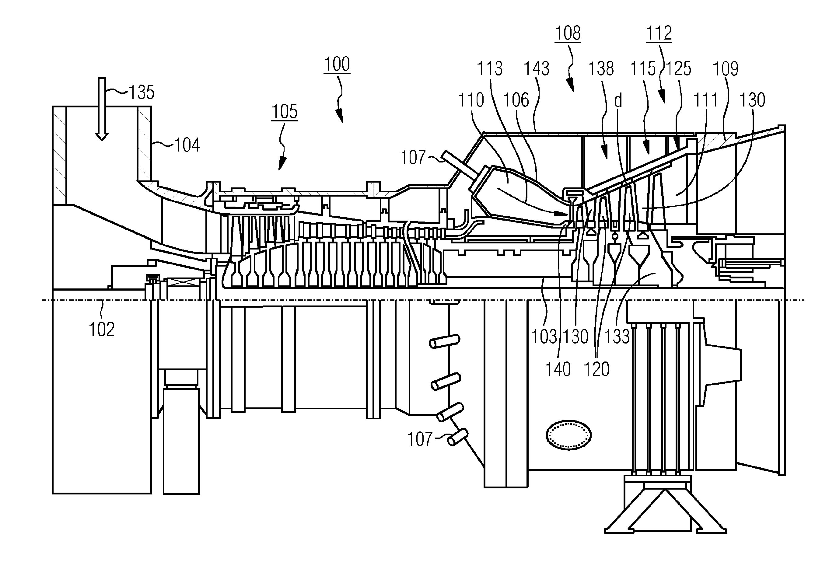
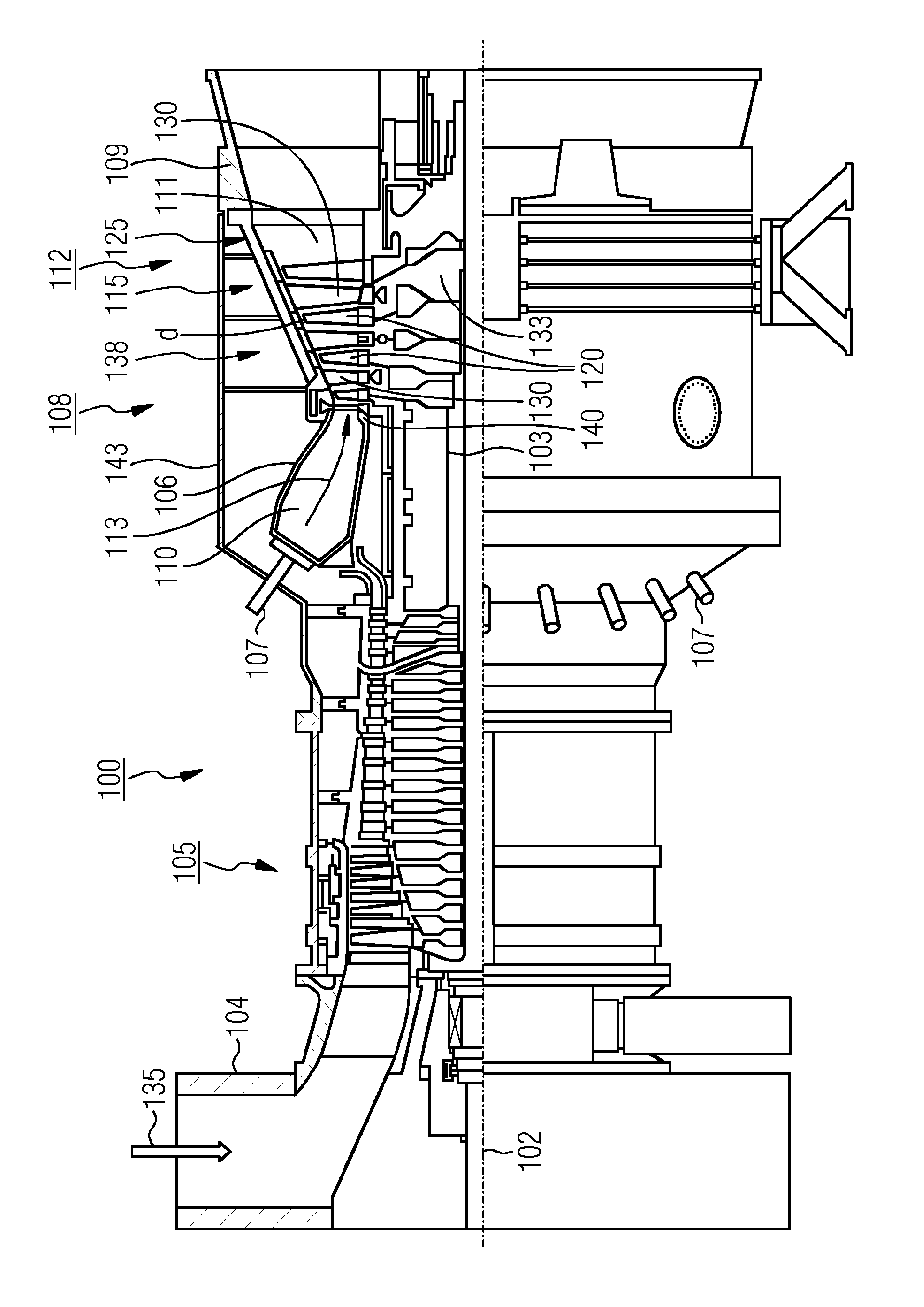
[0025]The FIGURE shows a turbine 100, in this case a gas turbine, in a longitudinal partial section. Inside, the gas turbine 100 has rotor 103 which is rotatably mounted around a rotational axis 102 (axial direction) and which is also referred to as a turbine rotor.

[0026]Arranged in series along the rotor 103 are an intake housing 104, a compressor 105, a toroidal combustion chamber 110—especially an annular combustion chamber 106—with a plurality of coaxially arranged burners 107, a turbine 108 and the exhaust gas housing 109.

[0027]The annular combustion chamber 106 communicates with an annular hot gas passage 111. Four series-connected turbine stages 112, for example, form the turbine 108 there. Each turbine stage 112 is formed from two blade rings. In the hot gas passage 111, a row 125 formed from rotor blades 120 follows a stator blade row 115, as seen in the flow direction of a working medium 113.

[0028]The stator blades 130 are fastened on the stator 143 in this case, whereas t...


PUM


Abstract

A method for minimizing the gap between a rotor, particularly a rotor vane, and a housing, particularly a housing of a turbine, wherein the gap between rotor and housing is adjustable is provided. The method includes displacing rotor and housing with respect to one another, to provide a simple way of minimizing the gap between rotor and housing. An output signal from a structure-borne sound monitoring system assigned to the rotor and / or housing is taken as a metric for the size of the gap and thus for setting a minimum gap.

Description

CROSS REFERENCE TO RELATED APPLICATIONS[0001]This application is the US National Stage of International Application No. PCT / EP2013 / 064901 filed Jul. 15, 2013, and claims the benefit thereof. The International Application claims the benefit of German Application No. DE 102012213016.0 filed Jul. 25, 2012. All of the applications are incorporated by reference herein in their entirety.FIELD OF INVENTION[0002]The invention relates to a method for minimizing the gap between a rotor, especially a rotor blade, and a housing, especially a housing of a turbine, wherein the gap between rotor and housing can be adjusted, especially by displacement of the rotor and the housing in relation to each other. It also relates to a turbine, especially a gas turbine, comprising a rotor, especially a rotor blade, and a housing, wherein the gap between rotor and housing can be adjusted by means of an adjusting device, especially by displacement of rotor and housing in relation to each other.BACKGROUND OF I...

Claims


Application Information

Patent Timeline
Patent Type & Authority Applications(United States)
IPC IPC(8): F01D11/22F01D11/12
CPCF01D11/122F01D11/22F05D2270/44F05D2270/334F01D11/20
Inventor LUTTENBERG, ANDREAS
Owner SIEMENS AG
Why Eureka
Try Eureka