Heat pipe and method for manufacturing the same

Inactive Publication Date: 2011-02-03
KUNSHAN JUZHONG ELECTRONICS
View PDF5 Cites 25 Cited by
  • Summary
  • Abstract
  • Description
  • Claims
  • Application Information

AI Technical Summary

Problems solved by technology
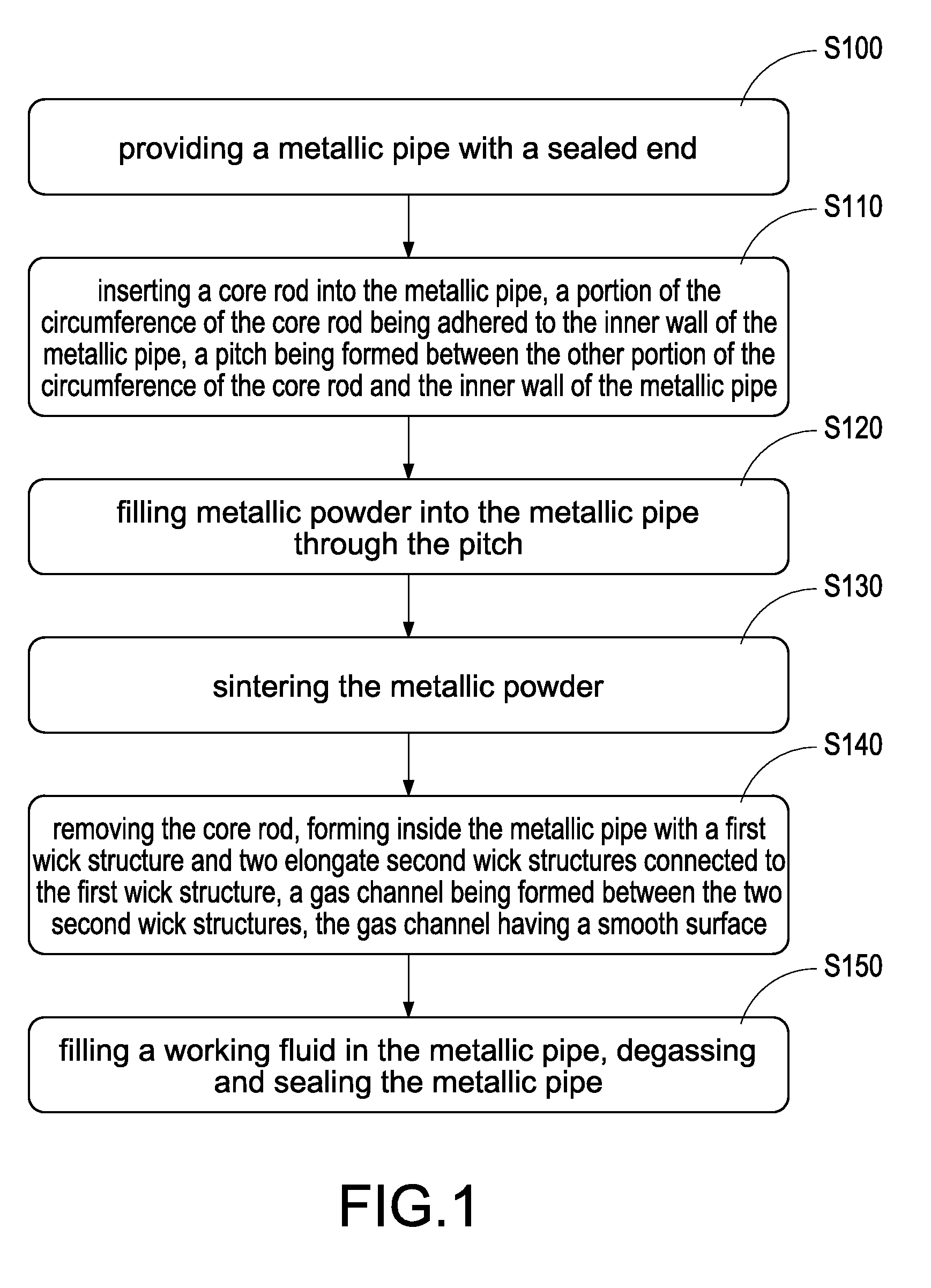
The heat-dissipating device comprised of an aluminum-extruded heat sink and a fan has become unable to satisfy the requirements for the heat dissipation of the current central processing unit.
However, the design of the internal structure of the heat pipe is dependent on the flowing speed of the gas and fluid within the heat pipe and the usage of

Method used


Image

  • Heat pipe and method for manufacturing the same
  • Heat pipe and method for manufacturing the same
  • Heat pipe and method for manufacturing the same

Examples


Example

[0031]The characteristics and technical contents of the present invention will be explained in more detail with reference to the accompanying drawings. However, the drawings are illustrative only but not used to limit the present invention.

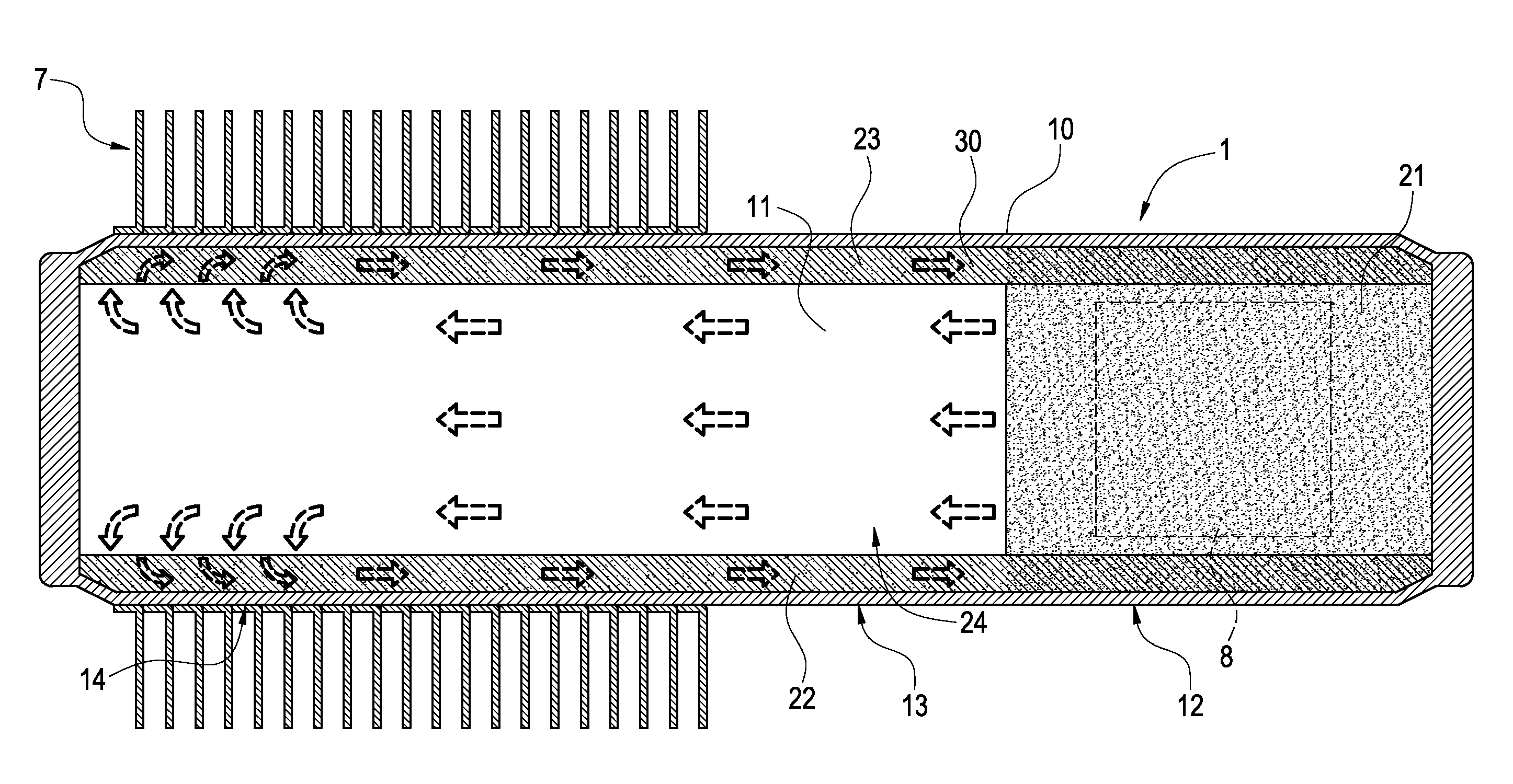
[0032]Please refer to FIG. 7. The present invention provides a heat pipe 1, which includes a metallic pipe 10, a wick structure 20 and a working fluid 30.

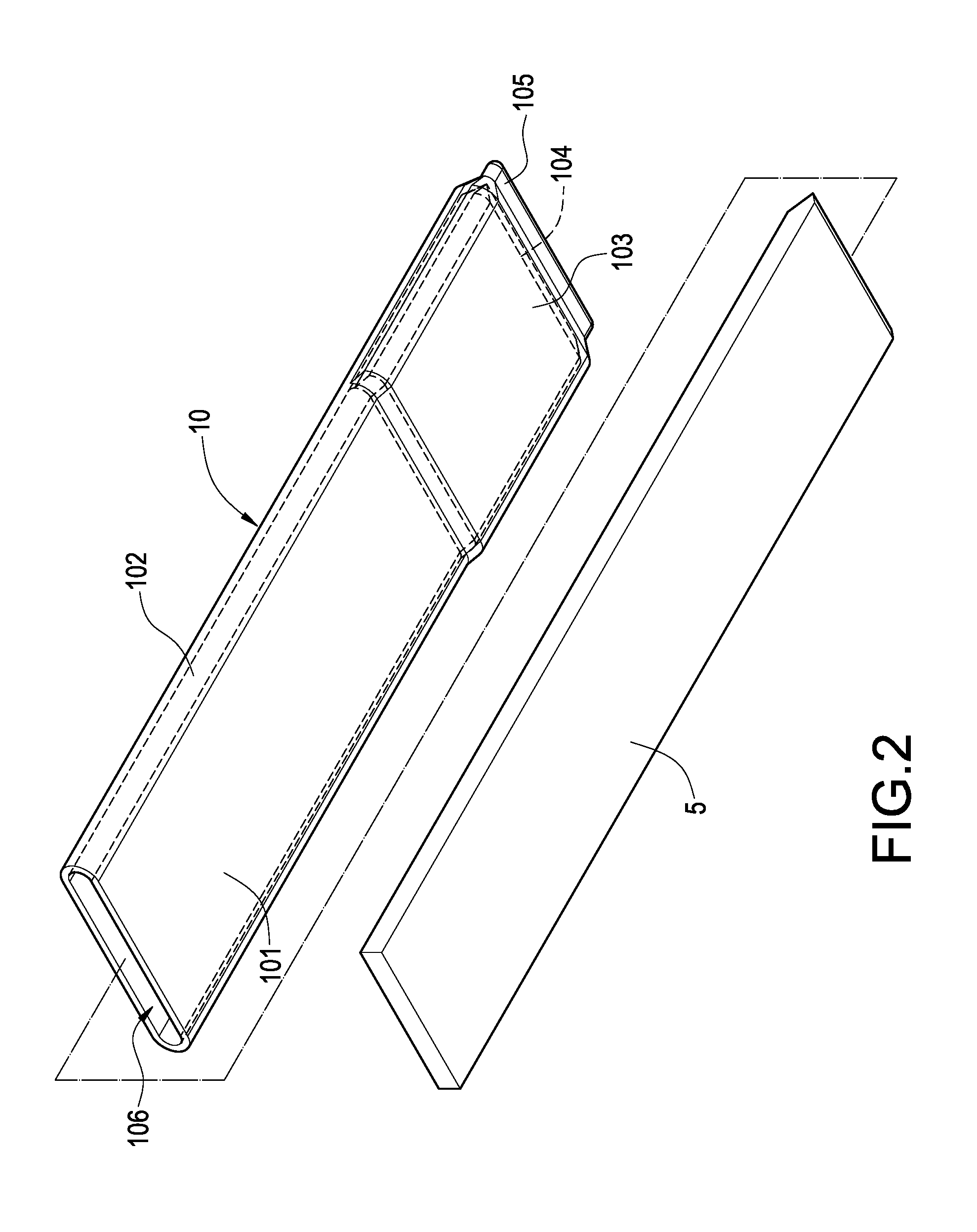
[0033]The metallic pipe 10 is pre-formed to have a flat profile. The cross section of the metallic pipe 10 is enclosed by two flat plates101 and two curved plates 102 (FIG. 5). The interior of the metallic pipe 10 has a sealed chamber 11 that is formed into an evaporating section 12, an adiabatic section 13 and a condensed section 14 along the lengthwise direction of the metallic pipe 10. The outer surface of the lower flat plate 101 of the evaporating section 12 protrudes to form a protrusion 103 (FIG. 4). The interior of the protrusion 103 is formed with a trough 104.

[0034]The wick structure 20...


PUM

PropertyMeasurementUnit
Timeaaaaaaaaaa
Efficiencyaaaaaaaaaa

Abstract

A heat pipe includes a metallic pipe, a wick structure and a working fluid. The interior of the metallic pipe has a sealing chamber, and is formed into an evaporating section, an adiabatic section and a condensing section along its lengthwise direction. The wick structure comprises a first wick structure and two elongate second wick structures connected to the first wick structure. The first wick structure is adhered to the inner wall of the evaporating section. The two second wick structures are separated from each other and adhered to the inner walls of the evaporating section, the adiabatic section and the condensing section. A gas channel is formed between the two second wick structures, and has a smooth surface. The working fluid is filled in the sealed chamber. By this arrangement, the space for the gas channel can be enlarged, thereby accelerating the flowing speed of the internal gas and enhancing the heat-conducting efficiency of the heat pipe.

Description

BACKGROUND OF THE INVENTION[0001]1. Field of the Invention[0002]The present invention relates to a heat pipe, and in particular to a heat pie that can be used to dissipate the heat of a heat-generating source of an electronic device and a method for manufacturing the same.[0003]2. Description of Prior Art[0004]With the continuous advancement of the operating speed of the central processing unit (CPU) of a computer, the amount of heat generated by the operation of the computer is increasing to a large extent. The heat-dissipating device comprised of an aluminum-extruded heat sink and a fan has become unable to satisfy the requirements for the heat dissipation of the current central processing unit. Thus, the manufacturers in this field propose novel heat pipes having better heat-dissipating efficiency. Then, this kind of novel heat pipe is combined with a heat sink to solve the problem of heat dissipation at the current stage. However, the design of the internal structure of the heat...

Claims


Application Information

Patent Timeline
IPC IPC(8): F28D15/04B21D53/02
CPCB22F2999/00F28D15/0233F28D15/046H01L23/427Y10T29/49353H01L2924/0002F28D15/0283B22F3/10B22F3/1283H01L2924/00
Inventor HUANG, YU-POKUO, TUNG-JUNG
Owner KUNSHAN JUZHONG ELECTRONICS
Why Eureka
Try Eureka