

Powder coated proppant and method of making the same
a technology of proppant and epoxy coating, which is applied in the direction of coating, fluid removal, borehole/well accessories, etc., can solve the problems of reducing the productivity of wells, reducing the flow of oil and gas, and complicated process used to make epoxy coating proppants
- Summary
- Abstract
- Description
- Claims
- Application Information
AI Technical Summary
Benefits of technology
Problems solved by technology
Method used
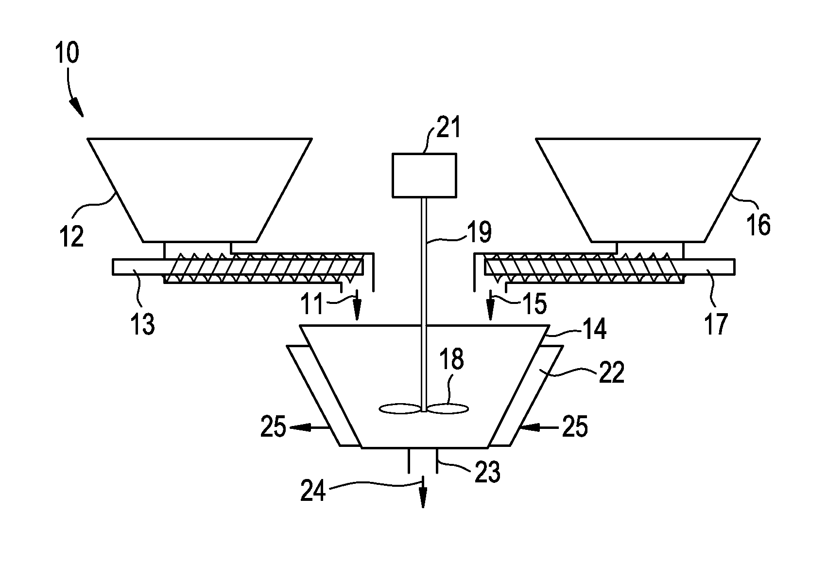
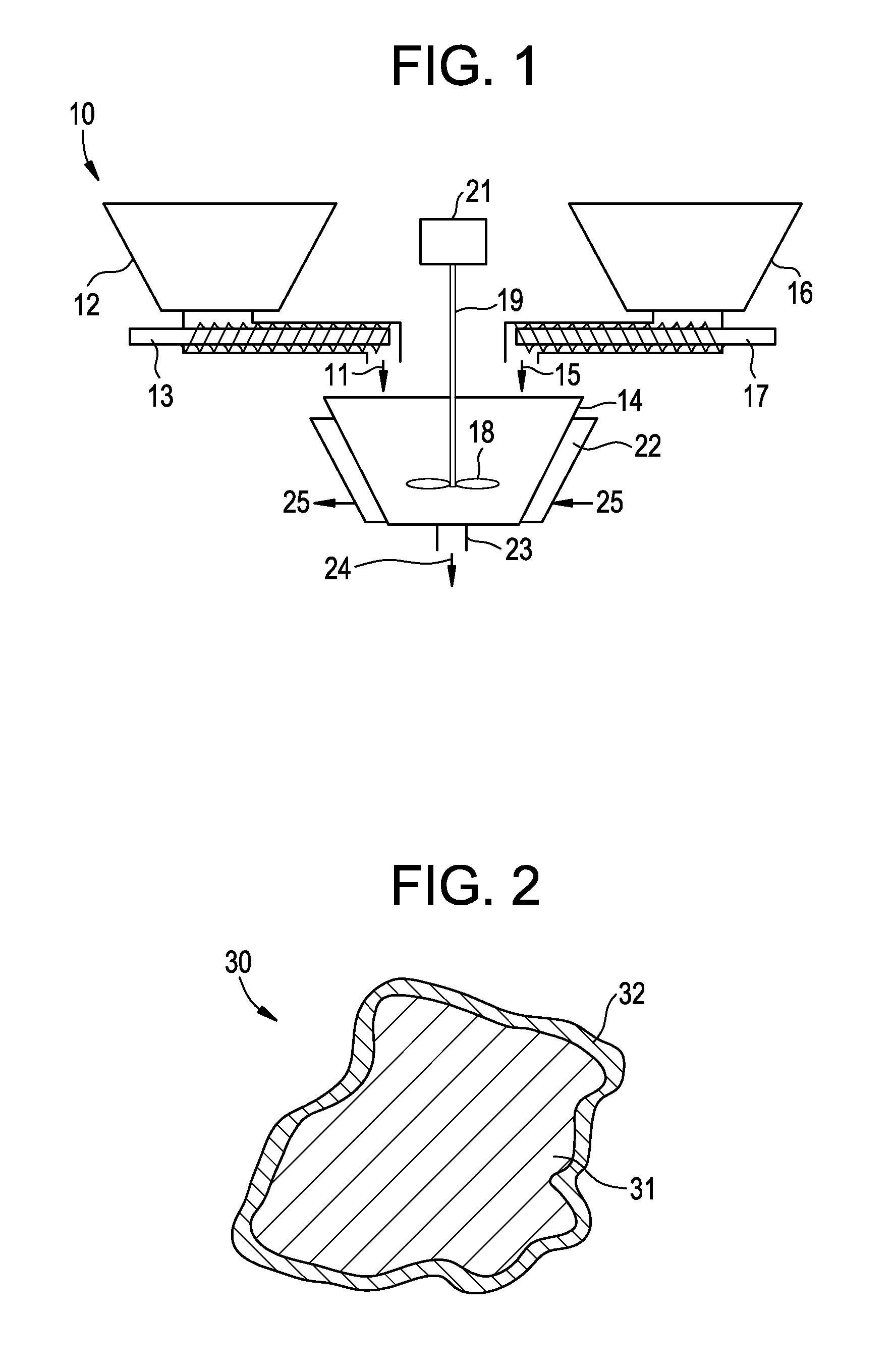
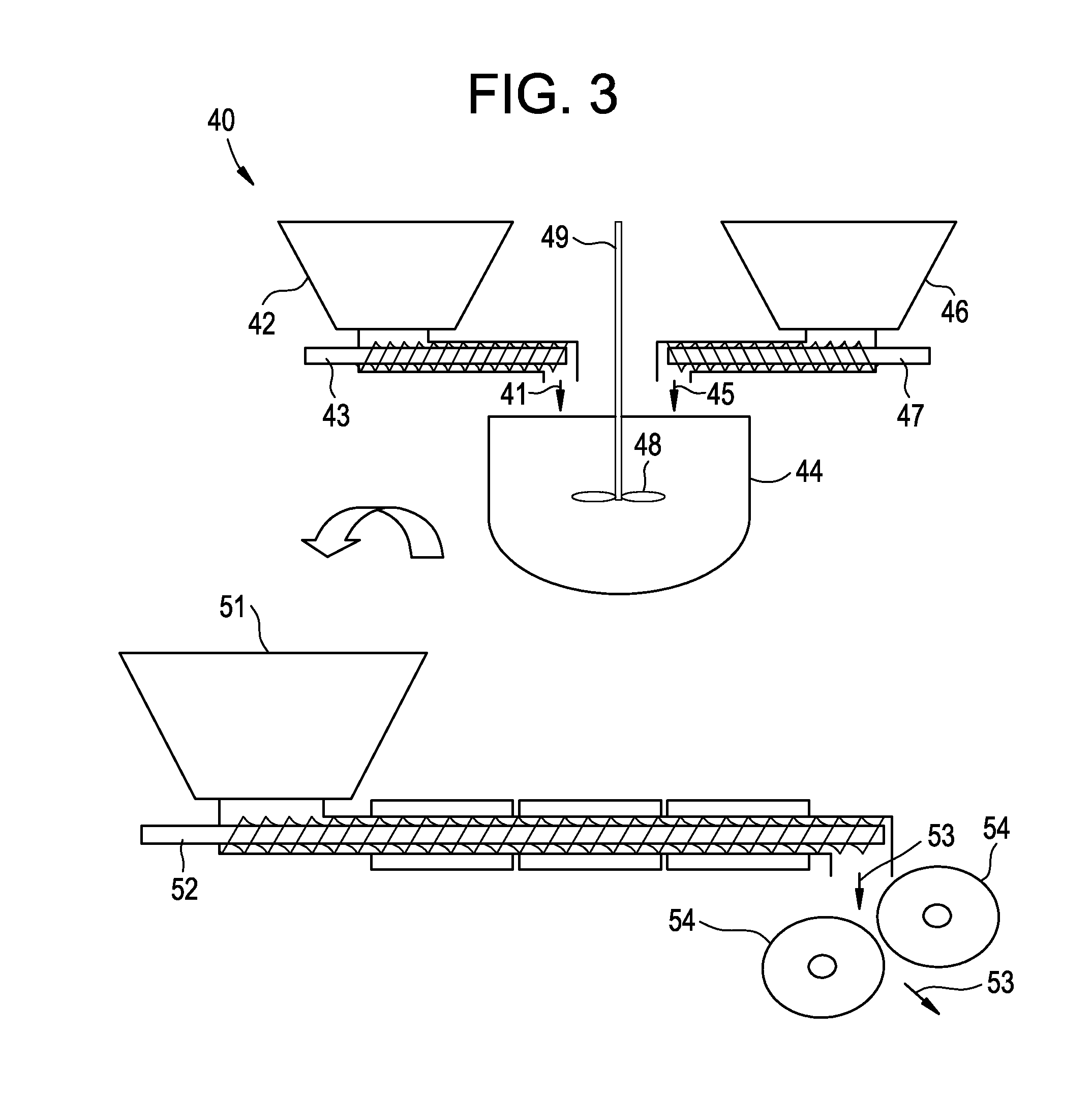
Image

Examples
example 1
[0031]A powder coating composition is prepared by blending 67.3 parts per hundred by weight (pph) of DER 664UE brand solid epoxy resin (commercially available from The Dow Chemical Company), with: 0.9 pph of Amicure CG-1200 brand curing agent; 0.5 pph of Epikure P101 brand catalyst; 1 pph of Modaflow III brand flow modifier; and 30.4 pph of Vansil W20 brand filler to produce a mixture which is extruded at 90° C., flaked, sieved, and then ground to a powder coating composition having an average diameter of about 30 micrometers. Then, 3 pph of the powder coating composition is blended with 97 pph of heated proppant sand at about 60° C. to about 140° C. for three to ten minutes and then cooled to produce an epoxy coating on the proppant sand.
[0032]In addition, 380 micrometer thick films are prepared by heating the powder coating composition to about 230° C. for two minutes so that tensile strength, percent break strain and modulus of the films can be determined by test method ASTM D638...
example 2
[0033]A powder coating composition is prepared by blending 66 parts per hundred by weight (pph) of DER 6508 brand solid epoxy resin (commercially available from The Dow Chemical Company), with: 2.1 pph of Amicure CG-1200 brand curing agent; 1 pph of Epikure P101 brand catalyst; 0.5 pph of Modaflow III brand flow modifier; and 30.4 pph of Vansil W20 brand filler to produce a mixture which is extruded at 90° C., flaked, sieved, and then ground to a powder coating composition having an average diameter of about 30 micrometers. Then 3 pph of the powder coating composition is blended with 97 pph of heated proppant sand at about 60° C. to about 140° C. for three to ten minutes and then cooled to produce an epoxy coating on the proppant sand.
[0034]In addition, 380 micrometer thick films are prepared by heating the powder coating composition to about 230° C. for two minutes so that tensile strength, percent break strain and modulus of the films can be determined by test method ASTM D638. Th...
example 3
[0035]A powder coating composition is prepared by blending 95.59 parts per hundred by weight (pph) of DER 642U brand solid epoxy resin (commercially available from The Dow Chemical Company), with: 2.27 pph of Amicure CG-1200 brand curing agent; 1.14 pph of Epikure P101 brand catalyst; and 1 pph of Modaflow III brand flow modifier to produce a mixture which is extruded at 90° C., flaked, sieved, and then ground to a powder coating composition having an average diameter of about 30 micrometers. Then 3 pph of the powder coating composition is blended with 97 pph of heated proppant sand at about 60° C. to about 140° C. for three to ten minutes and then cooled to produce an epoxy coating on the proppant sand. The onset Tg for this fully cured system is 110° C. and the percent conversion at gel point is about 29%.
PUM
| Property | Measurement | Unit |
|---|---|---|
| pressure | aaaaa | aaaaa |
| temperature | aaaaa | aaaaa |
| weight % | aaaaa | aaaaa |
Abstract
Description
Claims
Application Information