Item tracking in storage drawers

a technology of item tracking and storage drawers, applied in the field of unattended item tracking, can solve the problems of degrading or destroying the proper functioning of the object identified

Inactive Publication Date: 2011-02-03
WEAVER FREDERICK MICHAEL
View PDF3 Cites 42 Cited by
  • Summary
  • Abstract
  • Description
  • Claims
  • Application Information

AI Technical Summary

Benefits of technology

[0022]The present invention relates to a tracking individual tools periodically used in the performance of work orders. The present invention utilizes the under surface of a drawer to mount at least one sensor that provides a representation of the support surface of the drawer below. For the top most drawer, the underside of the support cabinet provides the support surface needed for the top drawer sensor tracking. The sensor can be in a fixed position relative to the drawer below such that when the drawer below is opened to remove or replace a tool the sensor captures mosaic sensor areas such that the assembled mosaic sensor areas capture the current status of the entire area that passes below the fixed position sensors as the drawer below moves out then back into its closed position. Alternatively, the same end result of an updated plurality of mosaic sensor areas can be achieved by a sensor platform that moves across the span of the storage surface then indexes and repeats the traverse capturing the adjacent strip of mosaic sensor areas and so forth until the entire storage surface is cataloged. In this embodiment the closed drawer need not move rather the sensor platform moves in an orderly manner as required. Both embodiments are similar to an aerial photo survey of a land area, which after image processing, results in a land surface view that can be further processed to derive thematic details. For the tool tracking application the goal is to identify empty tool template locations that should be filled at the time of work order close out or on query. Reporting such empty tool template locations alerts the responsible individual to the problem and the present invention can be linked into the work order close out process such that a close out is prohibited if a single tool is not in its storage location.

Problems solved by technology

The holes are of such a small diameter and sufficiently deep depth that they do not interfere with or detract from the function of the object identified, but any attempt to remove them by grinding or otherwise, degrades or destroys the proper functioning of the object identified.

Method used


Image

  • Item tracking in storage drawers
  • Item tracking in storage drawers
  • Item tracking in storage drawers

Examples


Embodiment Construction

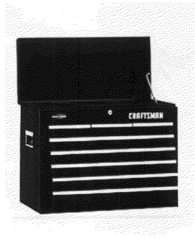
[0033]While the preferred embodiments taught are focused on tool tracking in storage drawers, the same invention enables the tracking of items stored in drawers such as medical supplies or jewelry. One skilled in the art will quickly recognize variations to the basic disclosed art which relate to alternative embodiments that are within the spirit of the disclosed art herein.

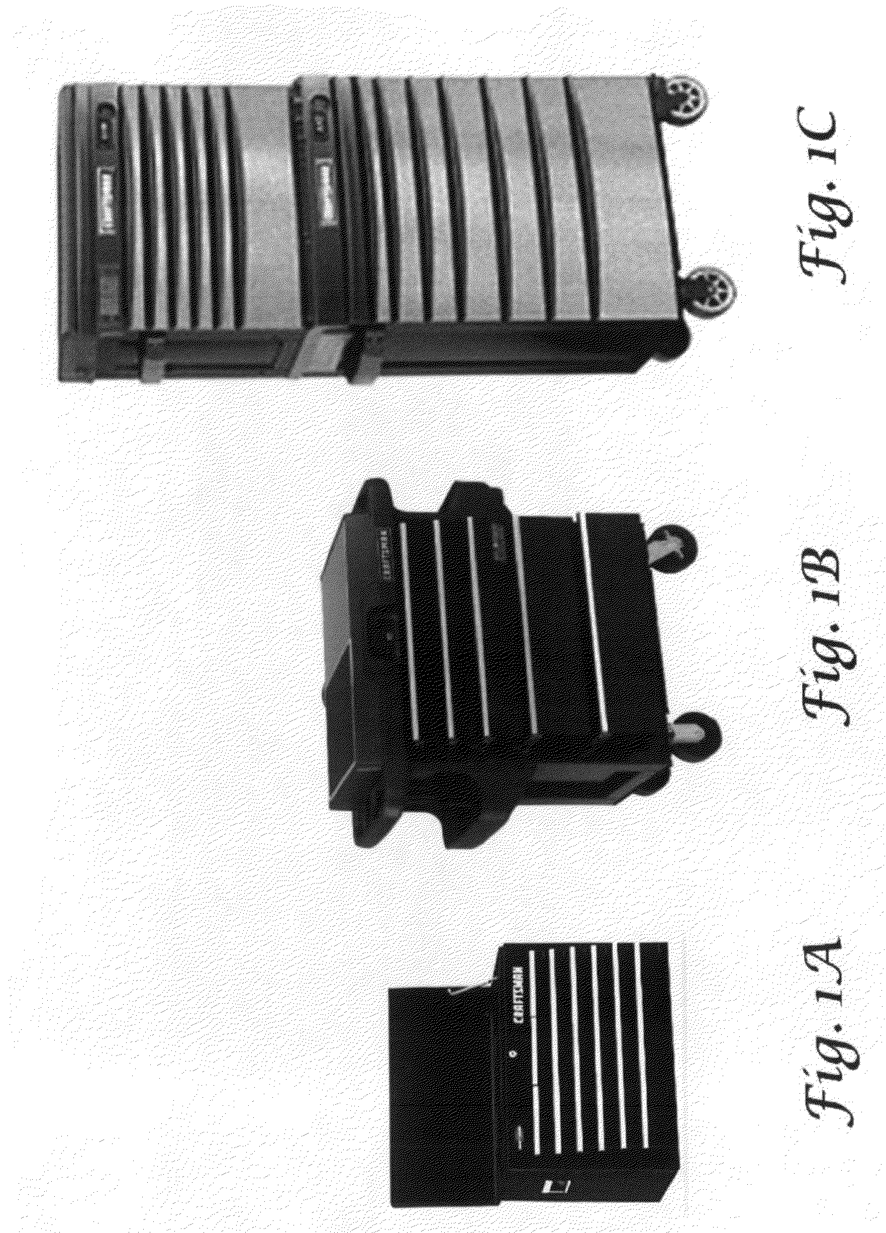
[0034]FIGS. 1A, 1B and 1C illustrate representative multi-drawer storage units both fixed in location and on rollers. In each example there are a plurality of drawers. A central theme of the disclosed art is that a sensor element is positioned superior to the collection of items to be monitored whether the drawer periodically moves out and back providing the sensor element area coverage of the storage area or a two-degree of movement X-Y platform moving sensor element is implemented.

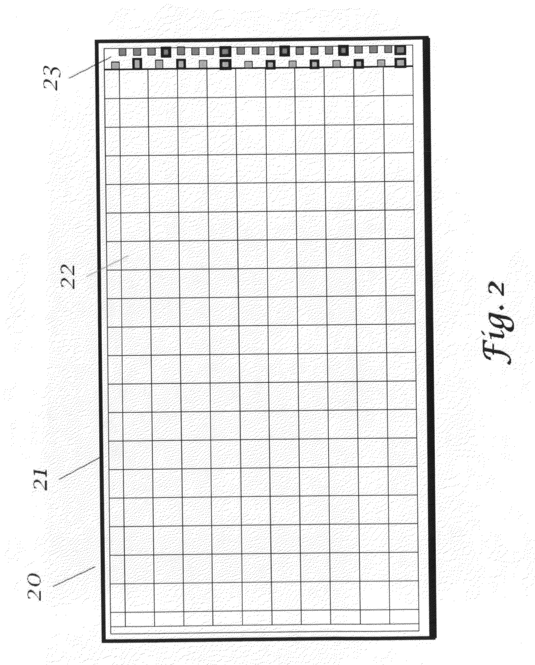
[0035]FIG. 2 illustrates how the area within a storage element 20, a drawer, is physically bounded by a wall 21 creating the storage...


PUM


Abstract

An item monitoring system for tracking and reporting absence of items such as tools from assigned storage locations. Non-contact sensors are used to capture a mosaic of sensed areas that are processed and compared to previous sensed areas identifying change in the presence or absence of items. When a change is detected the item inventory for the storage location is changed to reflect latest status of present or absent. Scaled to a plurality of storage drawers the item monitoring system provides automatic item inventory status for large storage cabinets which may be linked to a central processing system or queried by hand held terminal.

Description

FIELD OF THE INVENTION[0001]The present invention relates to unattended item tracking, such as tool tracking, providing awareness of missing tools from their storage drawers within storage cabinets.BACKGROUND OF THE INVENTION[0002]After depot or flight line maintenance work orders one or more tools could remain in an airframe causing the airframe to crash during its mission. The resultant loss of life and property, including third party losses on the ground, is both tragic and endangers mission critical operations.[0003]A wide variety of efforts have been undertaken to insure that all tools are replaced to their assigned storage locations typically focused on manual inventory reviews of each drawer to insure that all tools used for a job are back in their storage location or involving marking each tool with a code that is read by a scanner or by RFID tag associated with each tool. Manually based tracking of tools is a time consuming activity at the end of each work order and is subj...

Claims


Application Information

Patent Timeline
Patent Type & Authority Applications(United States)
IPC IPC(8): G08B13/14
CPCG08B21/24B25H3/00
Inventor WEAVER, FREDERICK MICHAEL
Owner WEAVER FREDERICK MICHAEL
Why Eureka
Try Eureka