Method of operating electromechanical pixels

Active Publication Date: 2011-02-03
PAKHCHYAN EDWARD
View PDF12 Cites 4 Cited by
  • Summary
  • Abstract
  • Description
  • Claims
  • Application Information

AI Technical Summary

Benefits of technology

[0009]The present invention provides efficient and reliable operating methods for an array of electromechanical light modulators. These operating methods

Problems solved by technology

The prior art operating methods of SLMs require electromechanical pixels with complex mechanical structures and tight mechanical tolerances.
Current manufacturing technology for large area flat panel displays that use glass substrates cannot meet these requirements.
Also, prior a

Method used


Image

  • Method of operating electromechanical pixels
  • Method of operating electromechanical pixels
  • Method of operating electromechanical pixels

Examples


Example

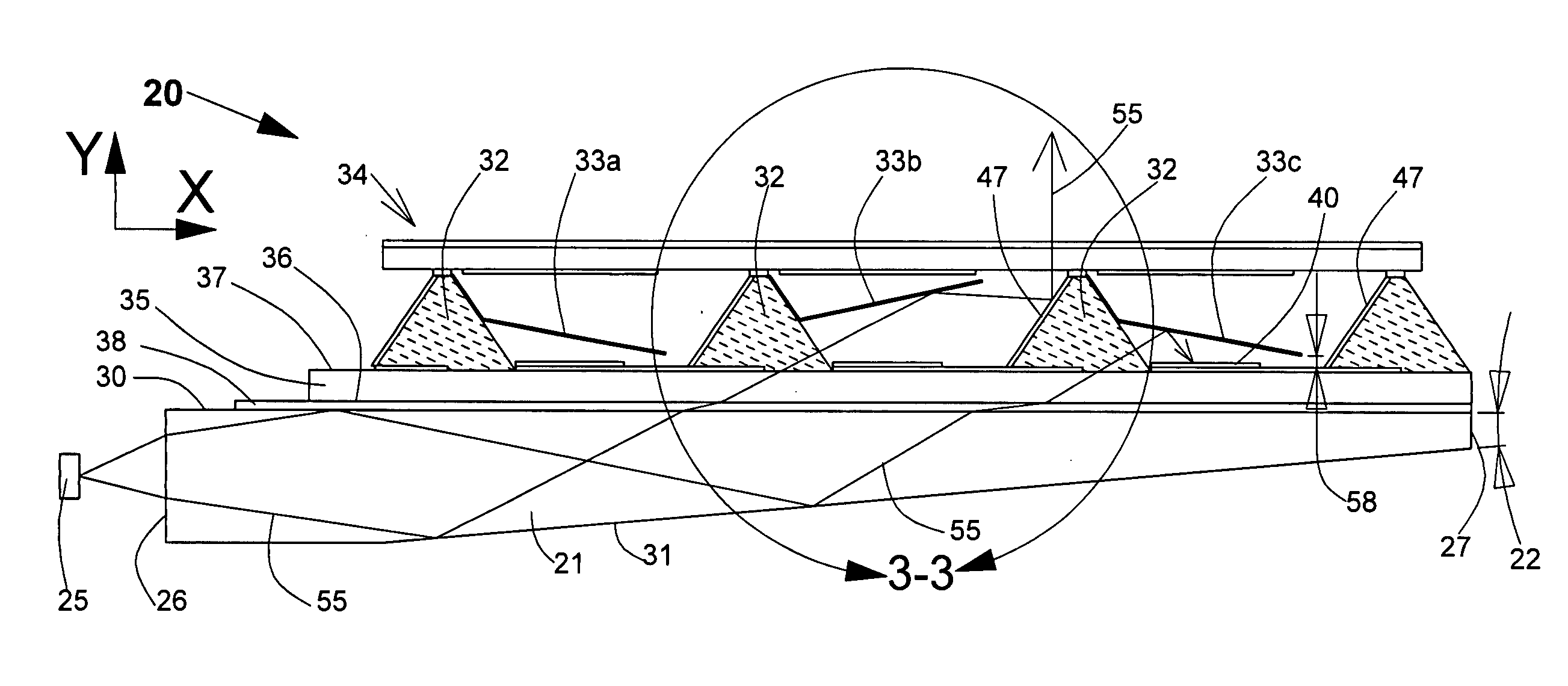
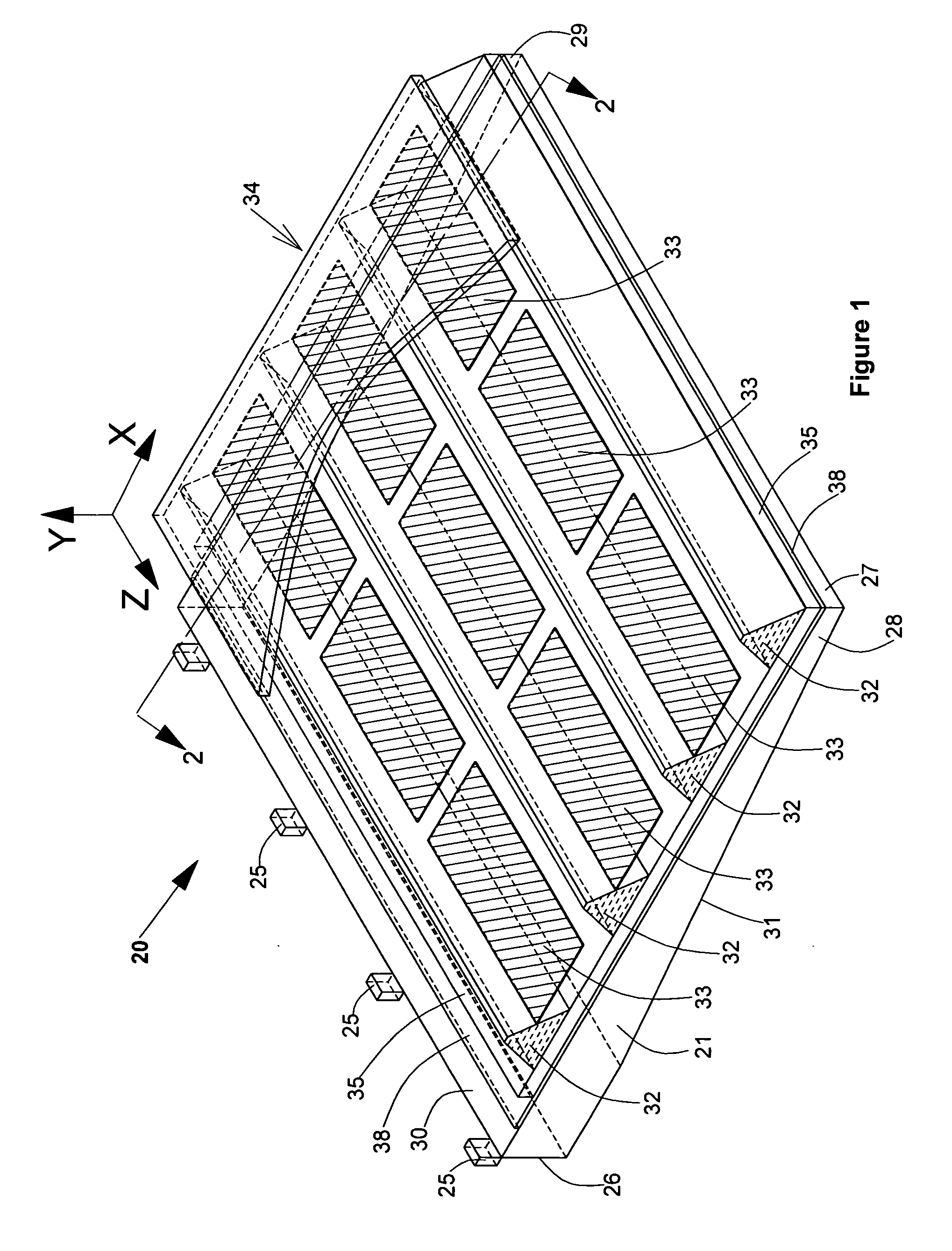
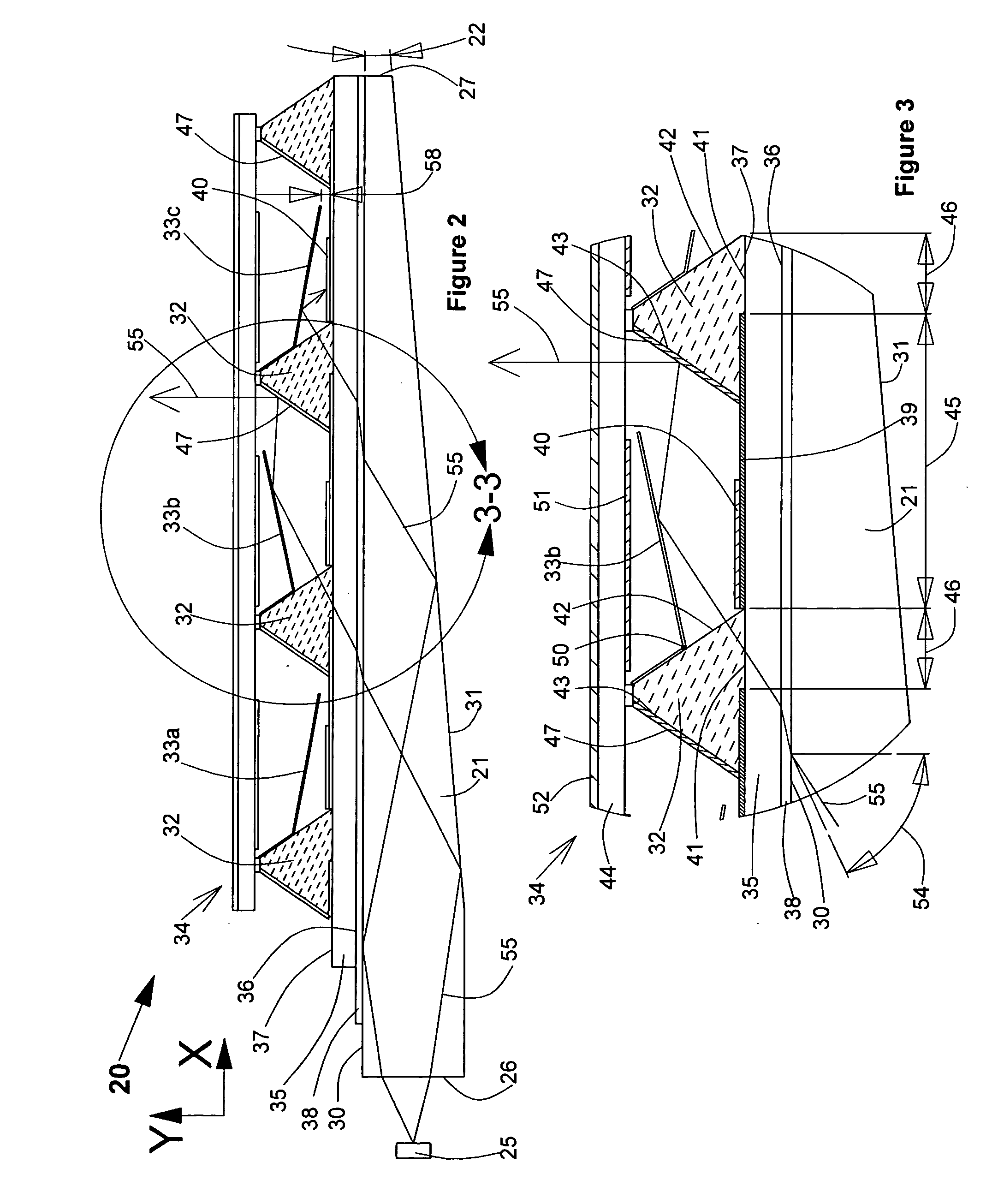
[0018]FIGS. 1 through 3 of the drawings illustrate the construction and optical functionality of a display panel 20. Referring to FIGS. 1 and 2 the display 20 includes a rectangular optical waveguide 21 that is substantially wedge-shaped cross section. Waveguide 21 is preferably constructed from acrylic or other optically transparent material, having a refractive index n1 with a value between 1.49 and 1.6 and comprises parallel first and second end surfaces 26 and 27 that are joined by parallel side surfaces 28 and 29 (see FIG. 1). Waveguide 21 also includes an upper surface 30 and a lower surface 31 converging with upper surface 30. Display 20 also includes a substrate 35 constructed from a substantially transparent material such as glass having a refractive index n2 with a value between 1.49 and 1.6. Lower surface 36 of substrate 35 is optically coupled to the upper surface 30 of waveguide 21 via an optical layer 38 formed from a fluoropolymer or other substantially transparent ma...


PUM


Abstract

Operating methods of an array of electromechanical pixels resulting in efficient and reliable operation of light modulating elements. The invention simplifies the design of electromechanical light modulators and permits the construction of large size displays with greater mechanical tolerances on glass substrates.

Description

RELATED U.S. PATENT DOCUMENTS[0001]Ser. No. 12 / 079,527 Mar.27, 2008 “PLASMA ADDRESSED MICRO-MIRROR DISPLAY” which is included here as reference.TECHNICAL FIELD OF THE INVENTION[0002]The present invention relates generally to displays. More particularly the invention concerns displays comprising electromechanical picture elements actuated by electrostatic force for modulating light to display motion images. More specifically the invention is directed to the operating methods of an array of electromechanical picture elements.BACKGROUND OF THE INVENTION[0003]Operating methods of electromechanical pixels are known from spatial light modulators (SLM) for projection displays. Prior art SLMs for projection displays comprise an array of micro-mirrors constructed on a semiconductor backplane. In prior art SLMs, each electromechanical pixel comprises a micro-mirror that is mounted on a pair of hinges above a semiconductor substrate, and a pair of address electrodes with associated drive elect...

Claims


Application Information

Patent Timeline
IPC IPC(8): G09G3/34G02B26/00G02B26/02G09G5/00
CPCG02B6/005G02B26/0841G09G2320/10G09G2310/06G09G3/346
Inventor PAKHCHYAN, EDWARDMESROPIAN, HAIKPAKHCHYAN, SYUZI
Owner PAKHCHYAN EDWARD
Why Eureka
Try Eureka